Inertial Navigation System (INS) for Drones/UAVs
Inertial navigation systems (INS) for unmanned aerial vehicles face significant challenges in maintaining accurate positioning when sensor errors accumulate. Without correction, even high-grade IMUs experience drift of 0.1-1.0 degrees per hour in attitude and position errors growing quadratically with time—reaching 100-300 meters after just 10 minutes of GPS-denied flight. These errors propagate differently across diverse flight profiles, with high-dynamic maneuvers particularly susceptible to acceleration-induced biases.
The fundamental challenge lies in balancing sensor accuracy, computational efficiency, and error compensation mechanisms while operating within the strict size, weight, and power constraints of drone platforms.
This page brings together solutions from recent research—including non-linear sensor fusion filters that account for complex drone-load dynamics, zero-point offset calibration methods using dual vector measurements, and hybrid systems that integrate visual feedback with inertial data to reduce drift. These and other approaches demonstrate how modern UAV navigation systems can maintain positioning accuracy in GPS-denied environments while supporting mission-critical applications.
TABLE OF CONTENTS
1. Multi-IMU Redundancy for Drift Mitigation
Individual MEMS IMUs are prone to drift, making them unsuitable for long flights without GNSS signals. A practical solution is to use multiple IMUs together and combine their data in real-time to improve accuracy.
1.1. Multi-Sensor Arrays for Enhanced Performance
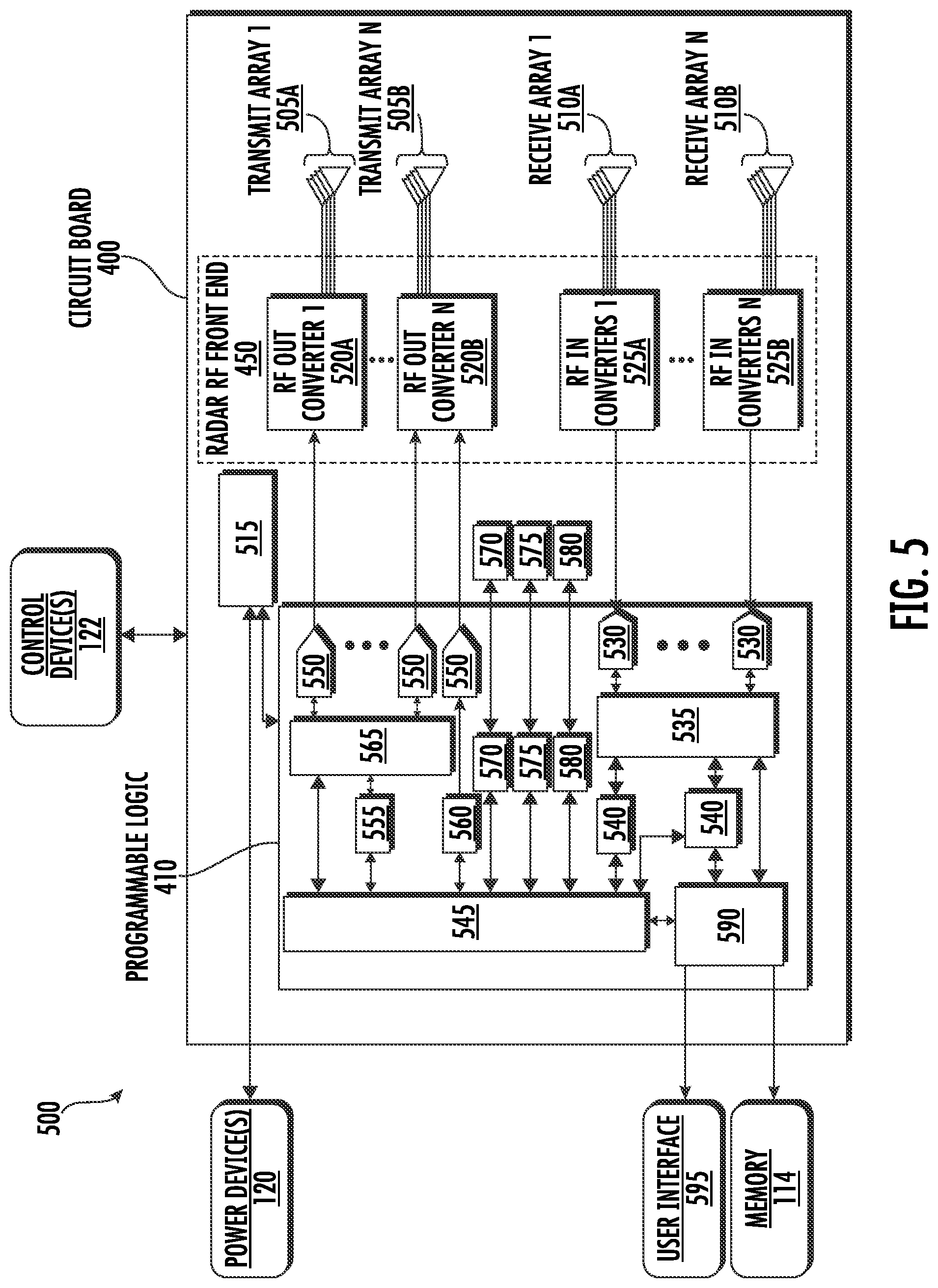
Orbital Research (a U.S. company specializing in high-performance frequency converters and RF components for the satellite communications (SATCOM) industry) developed an Enhanced-Performance multi-IMU array that demonstrates this approach. Their system can accommodate up to sixteen three-axis sensors mounted on a dual-sided board. The sensors are isolated from shock and synchronized at frequencies of 2 kHz or higher.
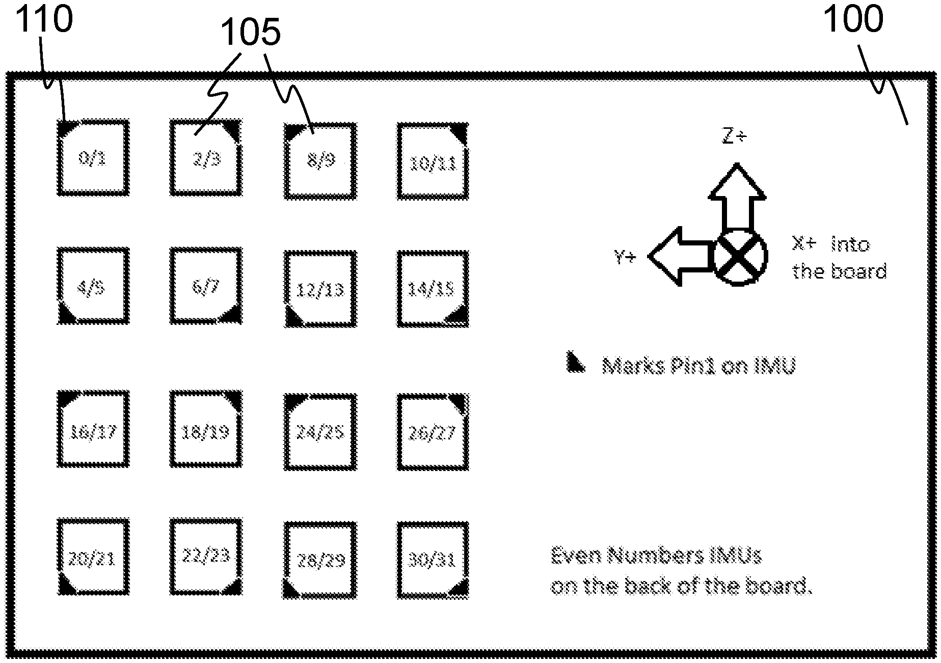
The system's firmware performs several key functions: it averages out noise from individual sensors, estimates bias during flight, and switches control between high-range and high-resolution sensor groups as needed. This multi-IMU approach achieves an angular random walk of 0.09°√h - nearly four times better than any single device. Despite this performance improvement, the entire system weighs less than 40 grams and consumes under 0.75 watts of power.
1.2. In-Flight Calibration Through Relative Rotation
Noise averaging alone cannot address drift that occurs when temperature changes or aging affects each sensor's scale factor. Atlantic Inertial Systems (a UK-based supplier of advanced guidance, stabilization, and inertial navigation products and systems for aircraft, vehicle, and land applications) developed an in-flight self-calibration via relative rotation technique to solve this problem. Their approach involves mounting one IMU fixed to the airframe while allowing a second IMU to rotate through known angles during normal flight maneuvers.
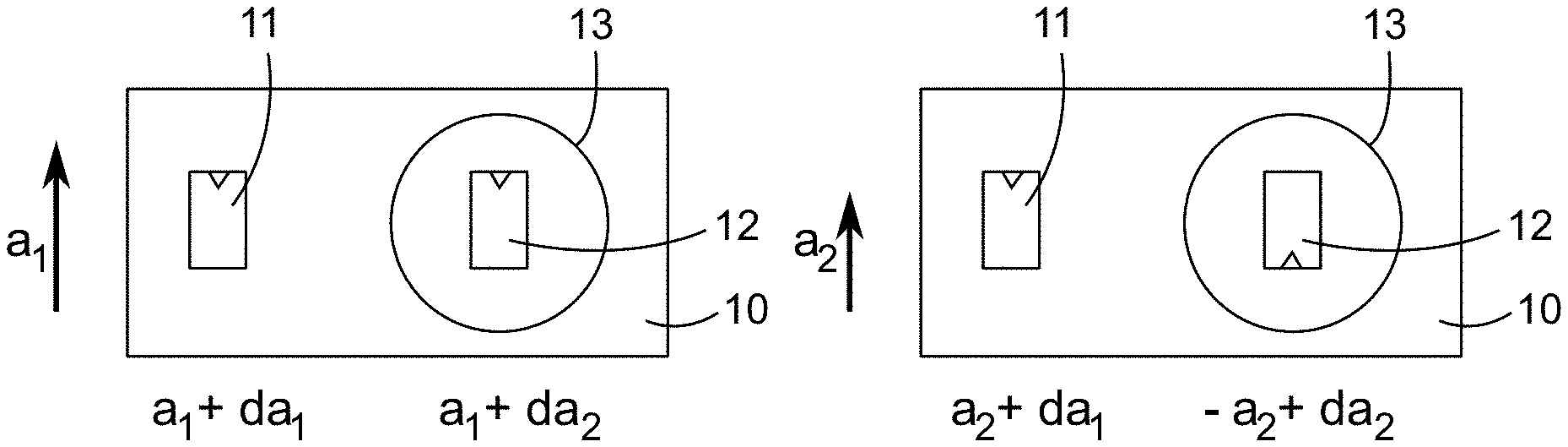
By capturing two sets of measurements under identical flight dynamics but different sensor orientations, the system creates a mathematically solvable equation for determining bias and scale factor errors. The system continuously updates these corrections in real-time, significantly reducing long-term drift. As an added benefit, the dual-sensor setup enables cross-validation between the two IMUs, allowing the system to detect and flag major sensor failures during flight.
1.3. Hardware-Level Redundancy and Failover Protection
Even perfectly calibrated sensors become useless if their processing systems fail. To address this critical vulnerability, Baidu USA (the American research division of Chinese tech giant Baidu) developed a dual-path IMU-MCU redundancy framework. This system pairs each of two IMUs with its own dedicated microcontroller, independent power supply, and separate GNSS timing input.
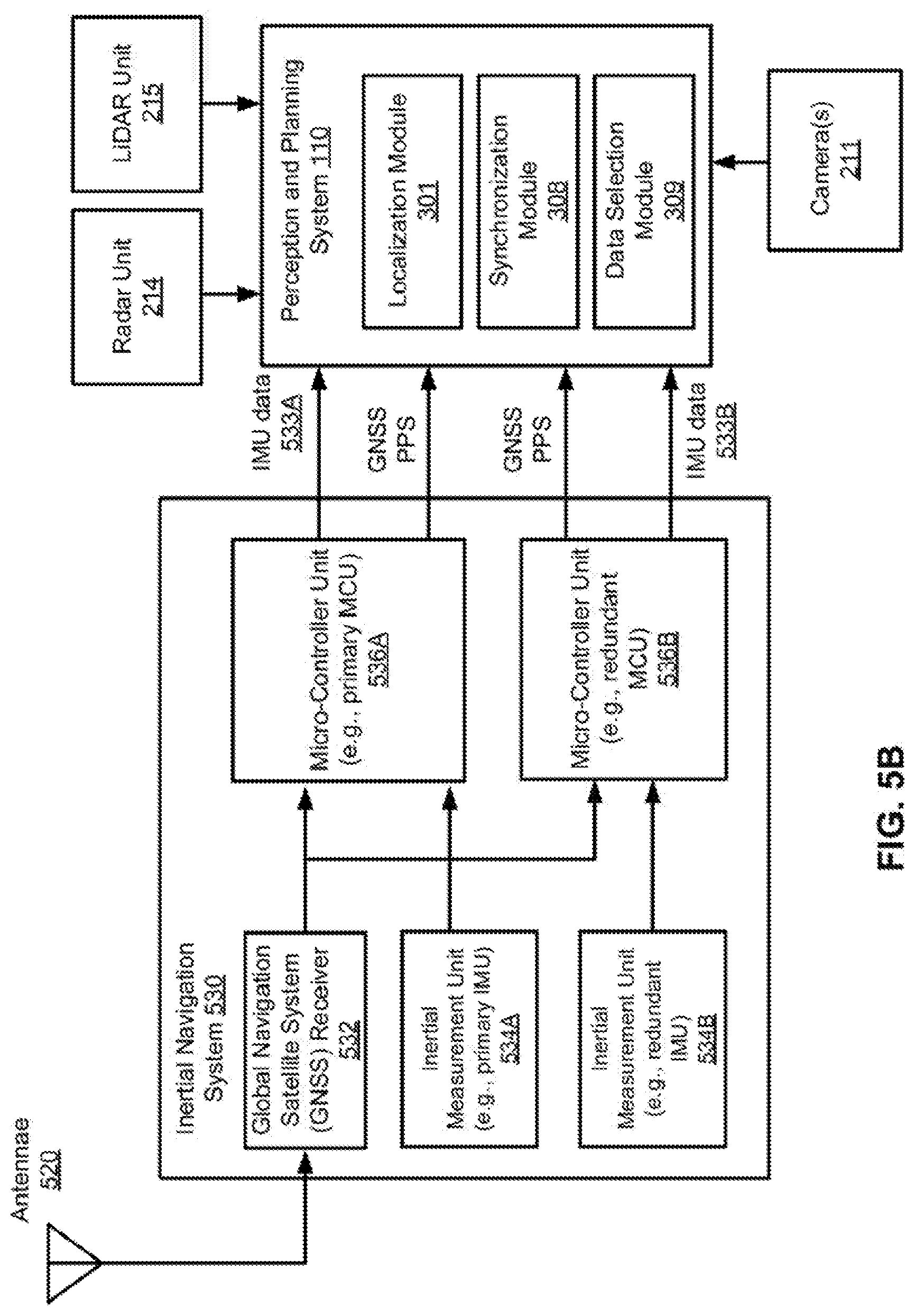
Both processing paths operate simultaneously, continuously cross-checking each other's outputs. If one path fails, the navigation estimator can seamlessly switch to the backup system in under a millisecond. This ultra-fast failover ensures uninterrupted navigation even when hardware components experience sudden failures during critical flight phases.
1.4. Adaptive Sensor Fusion Across Flight Envelopes
Different types of IMUs face a fundamental trade-off between accuracy and durability during extreme maneuvers. Low-noise 9-DOF (nine degrees of freedom) IMUs provide highly accurate readings by incorporating magnetometers for additional orientation data, but they saturate and become unreliable during violent maneuvers. In contrast, high-range 6-DOF (six degrees of freedom) units can withstand extreme accelerations and rotations, but they drift faster over time due to their reduced sensor complement.
AIQ Synertial (a UK-based company specializing in motion capture and inertial sensing technology) developed an error-compensating dual-range IMU module that addresses this limitation by combining both sensor types in a single package. The system intelligently fuses data from both IMUs depending on flight conditions. During normal flight operations within the 9-DOF unit's operational limits, the magnetometer-aided solution provides clean, accurate data that also helps correct errors in the 6-DOF stream.
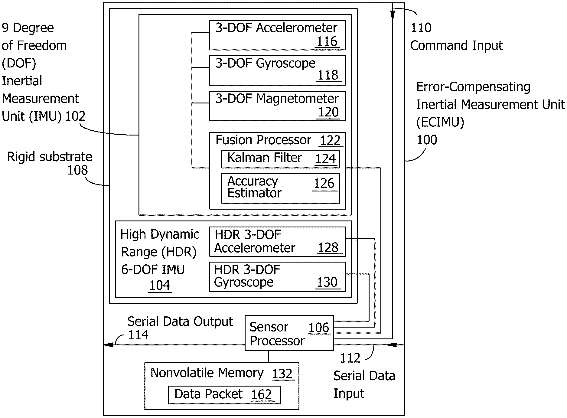
However, when the aircraft experiences high-G maneuvers that would saturate the sensitive 9-DOF sensors, the system automatically switches to rely on the more robust 6-DOF data. This approach maintains navigation continuity throughout the entire flight envelope, ensuring that pilots never lose critical orientation information during aggressive maneuvers.
1.5. Comprehensive Redundancy Strategy
These multi-IMU systems demonstrate that effective redundancy requires more than simply adding extra sensors. True redundancy involves intelligent orchestration of different sensor types, each contributing its strengths to overcome the limitations of others. The systems combine diverse sensor capabilities, continuously recalibrate themselves during flight operations, and wrap everything in fault-tolerant electronics that can handle component failures gracefully. This comprehensive approach extends mission duration far beyond what any individual MEMS sensor could achieve on its own.
2. In-Motion Calibration and Self-Healing Bias Compensation
2.1. In-Flight Zero-Point Compensation
Multiple IMUs can reduce noise through averaging, but each sensor still requires continuous calibration once the aircraft is in flight. Temperature changes, vibrations, and electromagnetic interference can cause individual sensors to drift from their zero points, leading to accumulated errors over time.
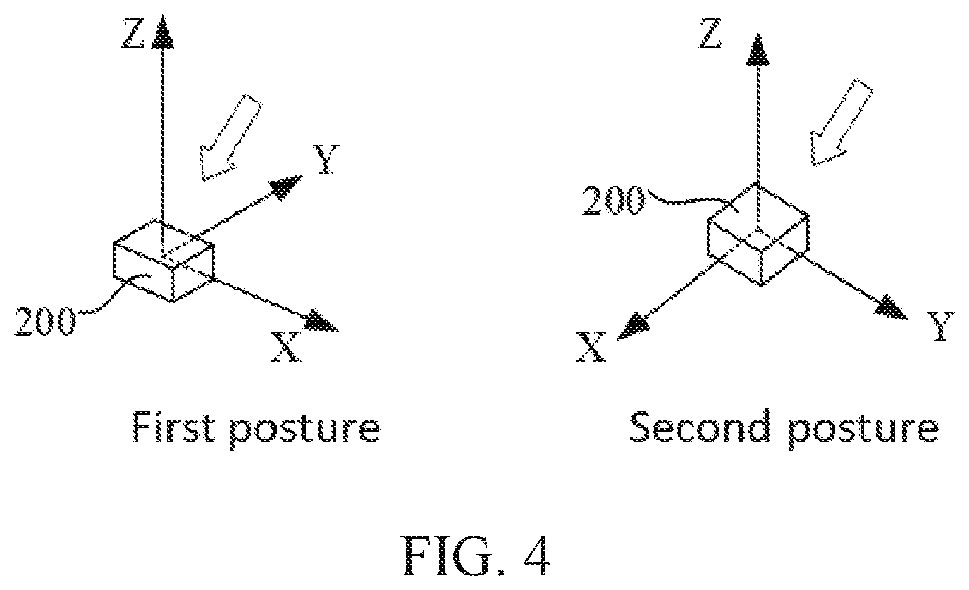
Reolink (a Chinese company specializing in security cameras and surveillance systems) developed an in-flight zero-point compensation algorithm that addresses this challenge. The system works by capturing gravity or geomagnetic field measurements at two different aircraft attitudes during normal flight operations. Using these reference measurements, the algorithm calculates the sensor offset errors and automatically subtracts them from all subsequent readings.
This approach allows the navigation system to maintain stable heading and attitude references throughout the mission, even when the aircraft experiences temperature swings, payload shifts, or electromagnetic interference from onboard systems. The continuous calibration happens transparently during flight without requiring any special maneuvers or external reference points.
2.2. Three-Vector In-Motion Alignment
Correcting zero-point offsets solves only part of the calibration challenge. The navigation system still needs to establish its orientation relative to a global reference frame while the aircraft is actively maneuvering.
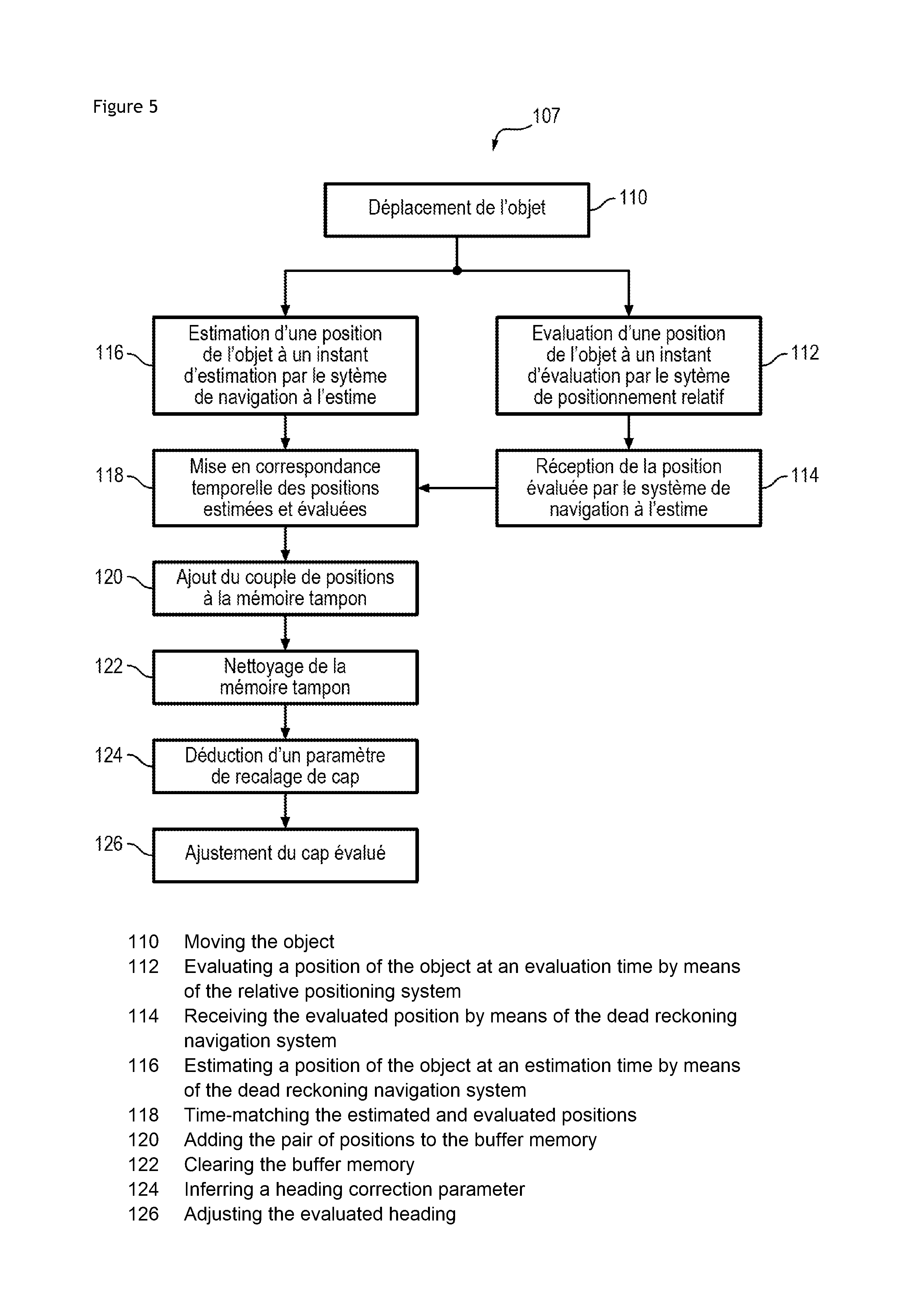
A three-vector in-motion alignment method addresses this requirement by cleverly using three different types of measurements that become available during normal flight operations. During turning maneuvers, the system uses gyroscope data to derive the gravity vector. When flying straight and level, it relies on accelerometer readings to determine the forward acceleration vector. Finally, when GNSS satellites are visible, it incorporates course-over-ground information as a third reference.
These three vectors are mathematically orthogonal to each other, providing enough information to fully establish the aircraft's orientation in three-dimensional space. The system can use this technique to initialize the INS at mission start, or to re-align the navigation system on the fly after events like mid-mission repositioning or temporary GNSS signal loss in urban canyon environments.
2.3. Real-Time Timing Synchronization
Even with proper alignment established, navigation systems face another challenge: timing mismatches between different sensor streams. IMUs and GNSS receivers often operate at different sampling rates, creating synchronization issues that can degrade fusion accuracy.
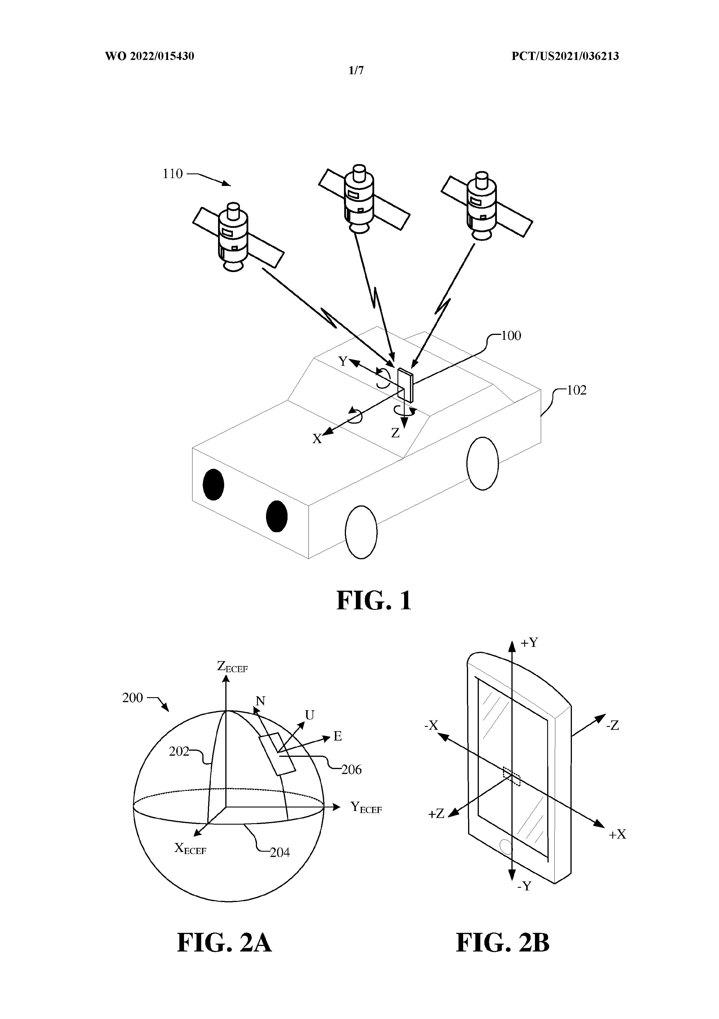
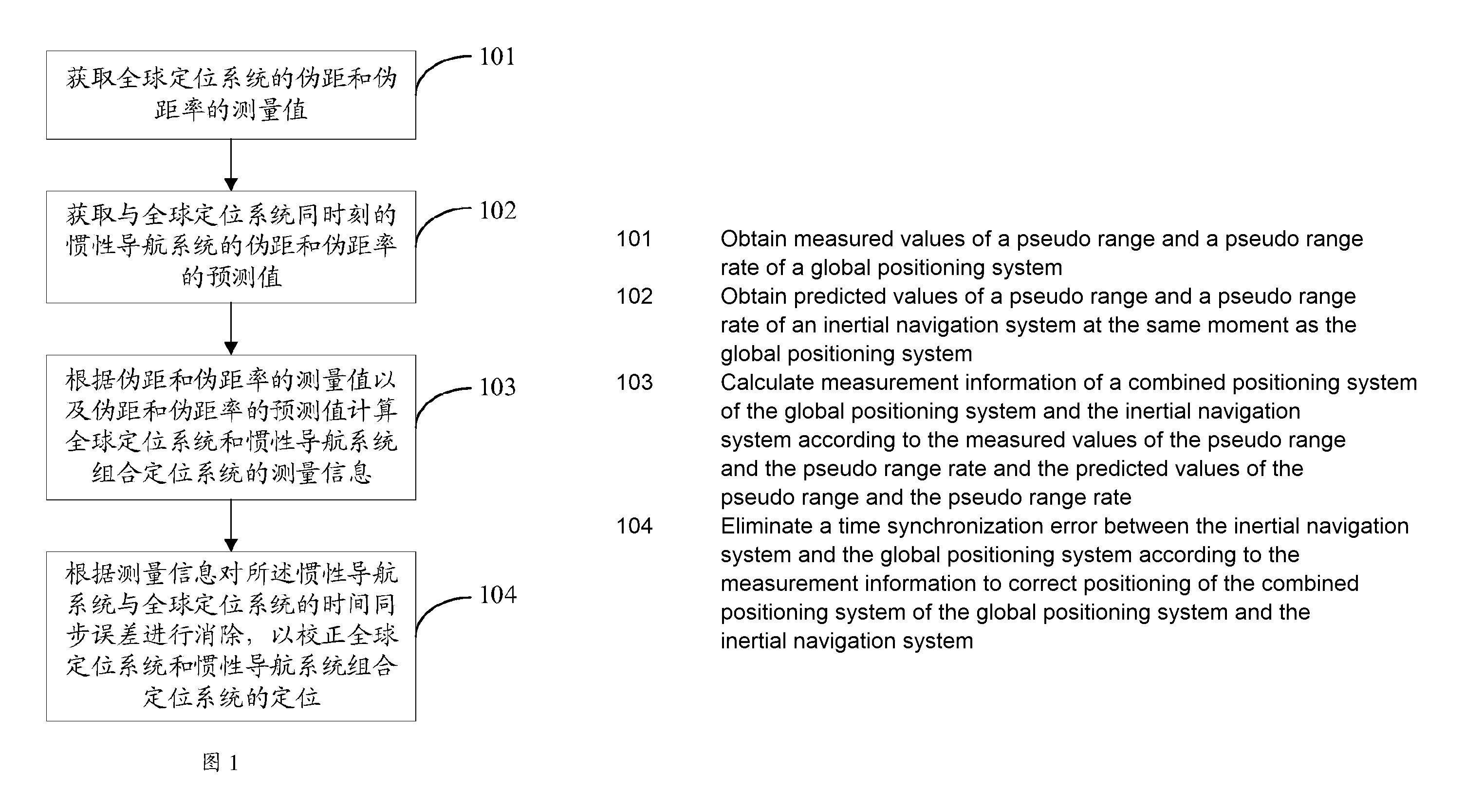
Oppo (a Chinese smartphone manufacturer known for fast-charging technology and camera innovations) developed an EKF-based time-offset estimator for tight GPS/INS fusion to solve this problem. Their approach treats the unknown time shift as part of the Kalman filter's state vector, allowing the system to estimate and correct timing offsets in real-time.
Dynamic Timing Correction Process
The system works by predicting satellite pseudorange measurements at the precise moment when inertial measurements are taken. It then resamples the GPS data using Taylor expansion to align it with the IMU timeline. The algorithm also incorporates lever-arm corrections to account for the physical separation between sensors and can optionally use machine-learned timing patterns from previous flights. This approach maintains tight coupling between GPS and INS data even when the two sensor systems operate at completely different sampling rates.
2.4. Velocity-Aware Gyroscope Calibration
Once timing synchronization is established, gyroscope scale factor errors become the primary source of long-term drift. Scale factor refers to how accurately a gyroscope converts its raw measurements into actual rotation rates - even small errors here can cause significant heading drift over time.
Hyundai AutoEver (the IT services subsidiary of Hyundai Motor Group, specializing in automotive software and connected vehicle technologies) developed a velocity-aware gyro scale-factor calibration scheme that addresses this challenge by learning the relationship between aircraft turn rate and scale factor errors early in each flight. The system monitors the UAV's maneuvers and builds a correction model based on how the gyroscope responds to different rotation speeds.
During flight operations, whenever the aircraft exceeds a predetermined turn rate threshold, the navigation filter automatically applies a velocity-dependent correction factor. This approach prevents heading drift from accumulating without requiring additional sensors or computationally intensive algorithms. The calibration happens continuously using the aircraft's normal flight maneuvers, maintaining accuracy throughout the mission.
2.5. Integrated Self-Correction Framework
These calibration techniques work together to transform the aircraft's natural flight movements into a continuous self-correction system. Instead of relying on external reference points or pre-flight calibration procedures, the navigation system learns and adapts using the maneuvers that occur during normal operations. This approach ensures that the inertial navigation core maintains its accuracy throughout the entire mission, regardless of environmental changes or flight duration.
3. Vision, Tag and LiDAR Aids for GPS-Denied Indoor Flight
Once a stable inertial navigation core is established, vision and LiDAR sensors can effectively handle navigation in confined indoor spaces.
3.1. Multi-Sensor Fusion for Centimeter-Level Indoor Accuracy
Samsung developed a multi-sensor EKF-based indoor navigation suite that integrates multiple complementary sensors on a single UAV platform. The system combines an IMU with dual tag readers, cameras facing both upward and downward, and optional altitude sensors.
At the core lies an extended Kalman filter that intelligently fuses data from all these sources. It processes visual odometry from the cameras, position fixes from detected tags, lateral positioning cues derived from edge detection, and includes a Mahalanobis gate to automatically reject outlier measurements. This comprehensive sensor fusion approach delivers centimeter-level accuracy for all six degrees of freedom (position and orientation) without requiring any pre-mission mapping of the environment.
The system's design philosophy replaces expensive spinning LiDAR units with a combination of low-cost cameras and passive reference tags. This makes the technology more accessible while maintaining the high precision needed for safe indoor flight operations.
3.2. Context-Aware Navigation for Moving Carriers
Operating from moving platforms presents unique challenges. When a drone operates from a moving carrier such as a ship or vehicle, the additional motion can confuse traditional SLAM (Simultaneous Localization and Mapping) systems. The challenge arises because the navigation system must distinguish between the carrier's movement and the drone's own flight dynamics.
Sony developed a context-aware sensor-prioritization logic that solves this problem by continuously monitoring the motion states of both the carrier platform and the UAV itself. The system then dynamically adjusts which sensors receive priority in the navigation filter. It distinguishes between absolute-frame sensors (like IMU and GPS, which measure motion relative to Earth) and local-frame sensors (like LiDAR and stereo cameras, which measure motion relative to nearby objects).
Intelligent Sensor Switching Logic
When the carrier is moving but the drone remains parked on deck, the system prioritizes inertial data from the IMU and GPS to maintain accurate positioning. However, once the drone takes off and the carrier stabilizes, the navigation filter shifts authority back to LiDAR and vision systems, which can provide more precise relative positioning for close-quarters maneuvering. This intelligent sensor switching ensures accurate navigation throughout the complex sequence of carrier motion, drone launch, and independent flight operations.
3.3. Image-Aided Attitude Stabilization for Optical Payloads
Drones carrying cameras or other optical equipment need extremely stable attitude control to capture clear images or maintain accurate pointing. Even small angular errors can cause significant image blur or targeting mistakes, especially when using telephoto lenses or precision sensors.
Safran Electronics & Defense (a French aerospace company specializing in navigation systems, optronics, and avionics for military and civilian applications) developed an image-aided inertial drift suppression system that addresses this challenge. The approach works by continuously comparing the live camera feed against a lightweight database of optical signatures stored onboard the aircraft.
Self-Learning Vision Correction
When the navigation system's uncertainty exceeds a predetermined threshold, the vision system calculates the angular offset between the expected scene and what the camera actually sees. This derived correction is then fed back into the inertial attitude filter, helping to suppress drift and maintain precise pointing. The onboard database updates itself during flight operations, learning new visual features as the mission progresses. This self-updating capability ensures that three-axis pointing accuracy remains tight throughout the entire mission without requiring periodic manual intervention from operators.
4. Infrastructure-Aided Indoor Localization and Precision Landing
Navigating close to obstacles requires different capabilities than actually landing in the same confined space. While precise maneuvering is one challenge, achieving a safe touchdown presents entirely different technical requirements.
4.1. Multi-Sensor Spatial Awareness Systems
Amazon Technologies (the R&D division of the e-commerce giant, specializing in logistics automation and drone delivery systems) developed a 360° multi-sensor suite that addresses both challenges simultaneously. Their system combines LiDAR sensors, time-of-flight ranging devices, and omnidirectional cameras to continuously measure distances to floors, ceilings, and walls in all directions.
The complete sensor package fits within a low-profile fuselage design, maintaining the aircraft's aerodynamic efficiency while providing comprehensive spatial awareness.
Flexible Docking Operations
For the landing phase, the system works with specially designed docking cradles that can accept the aircraft in multiple orientations. This flexibility enables hands-free recharging operations even when the drone cannot achieve a perfect approach angle due to space constraints or obstacle placement.
4.2. Radio-Based Triangulation for GNSS-Denied Environments
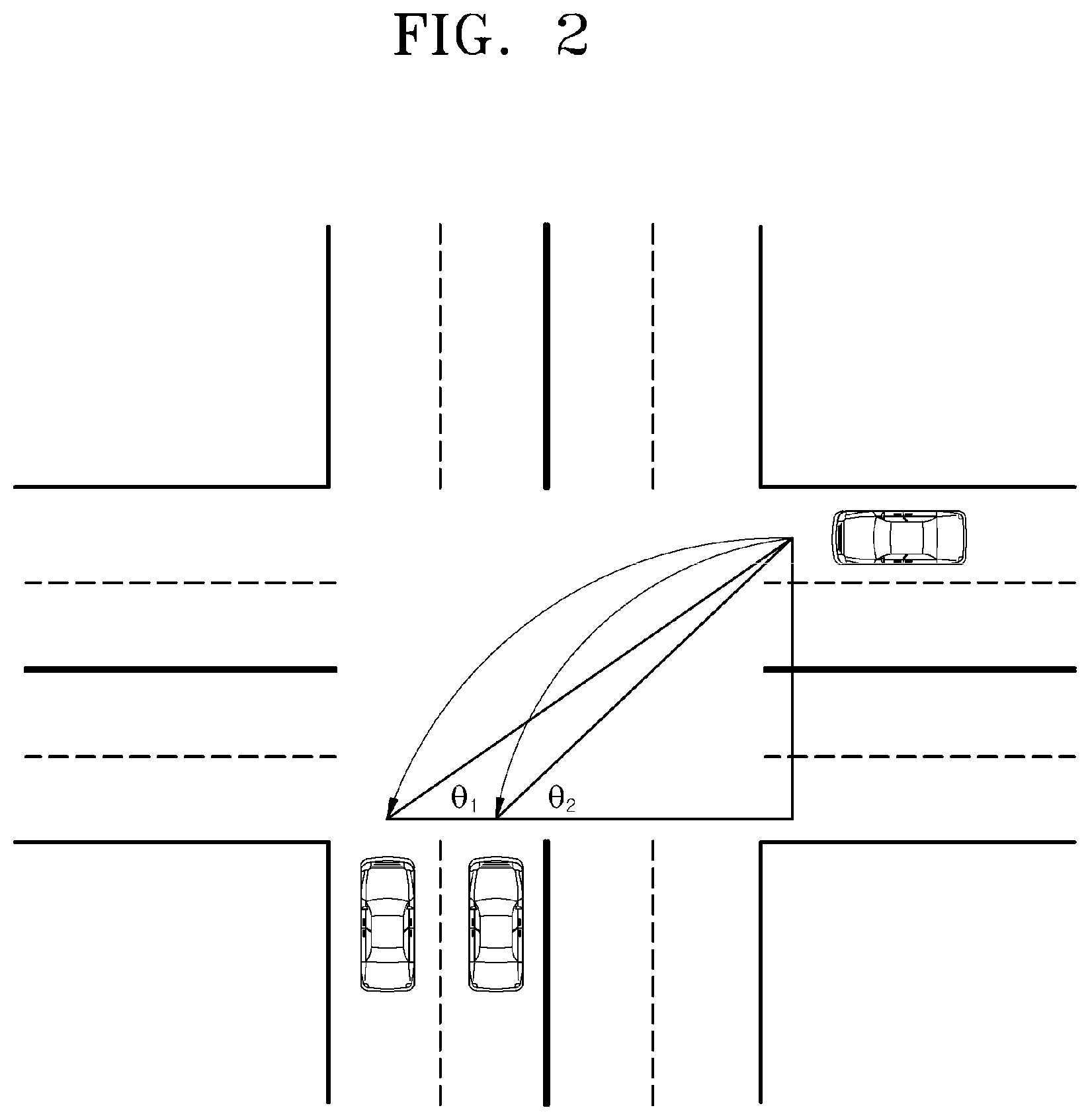
Rockwell Collins (a U.S. aerospace company specializing in avionics and communication systems for commercial and military aircraft) developed a two-radio time-of-flight triangulation system that enables precision landing without GNSS signals. The approach uses lightweight ground radios to determine the aircraft's horizontal position through triangulation measurements.

Core Positioning Mechanism
The system works by deploying two compact radio beacons at known locations near the landing site. The aircraft measures the time-of-flight to each beacon, providing distance measurements that can be triangulated into a precise horizontal position fix. For vertical positioning, the system integrates data from barometric sensors, radar altimeters, or laser rangefinders to determine altitude accurately.
Enhanced Accuracy Through Acquisition Orbits
To improve positioning accuracy, the aircraft can optionally fly an acquisition orbit around the landing area. This maneuver stretches the triangulation geometry, reducing dilution of precision and providing more reliable position fixes. During the actual descent phase, the navigation system fuses the radio-based position data with readings from the IMU, air-data sensors, and magnetometer to guide the aircraft safely to touchdown.
This lightweight approach replaces bulky ground-based radar systems with a pocket-sized radio kit that can be quickly deployed at remote or austere landing sites, making precision landings possible in locations where traditional navigation aids are unavailable.
4.3. UWB-Based Attitude Correction Systems
SYSNAV (a French company specializing in indoor positioning systems and inertial navigation technology) developed an attitude reset with UWB anchors that maintains heading accuracy without relying on magnetometers. The system works by combining inertial navigation data with periodic position fixes from ultra-wideband (UWB) anchor points deployed throughout the building.
Magnetometer-Free Navigation
When the navigation system detects that heading drift has exceeded acceptable limits, it uses the precisely known locations of UWB anchors to recalibrate the INS orientation. This approach eliminates the need for magnetometers, which can be unreliable in indoor environments due to steel structures and electrical interference. The periodic centimeter-level position fixes keep cumulative positioning errors within tens of centimeters across an entire building, maintaining navigation accuracy throughout extended indoor missions.
5. Multi-Antenna GNSS and Doppler-Supported Attitude Estimation
5.1. Distributed Antenna Ring Architecture
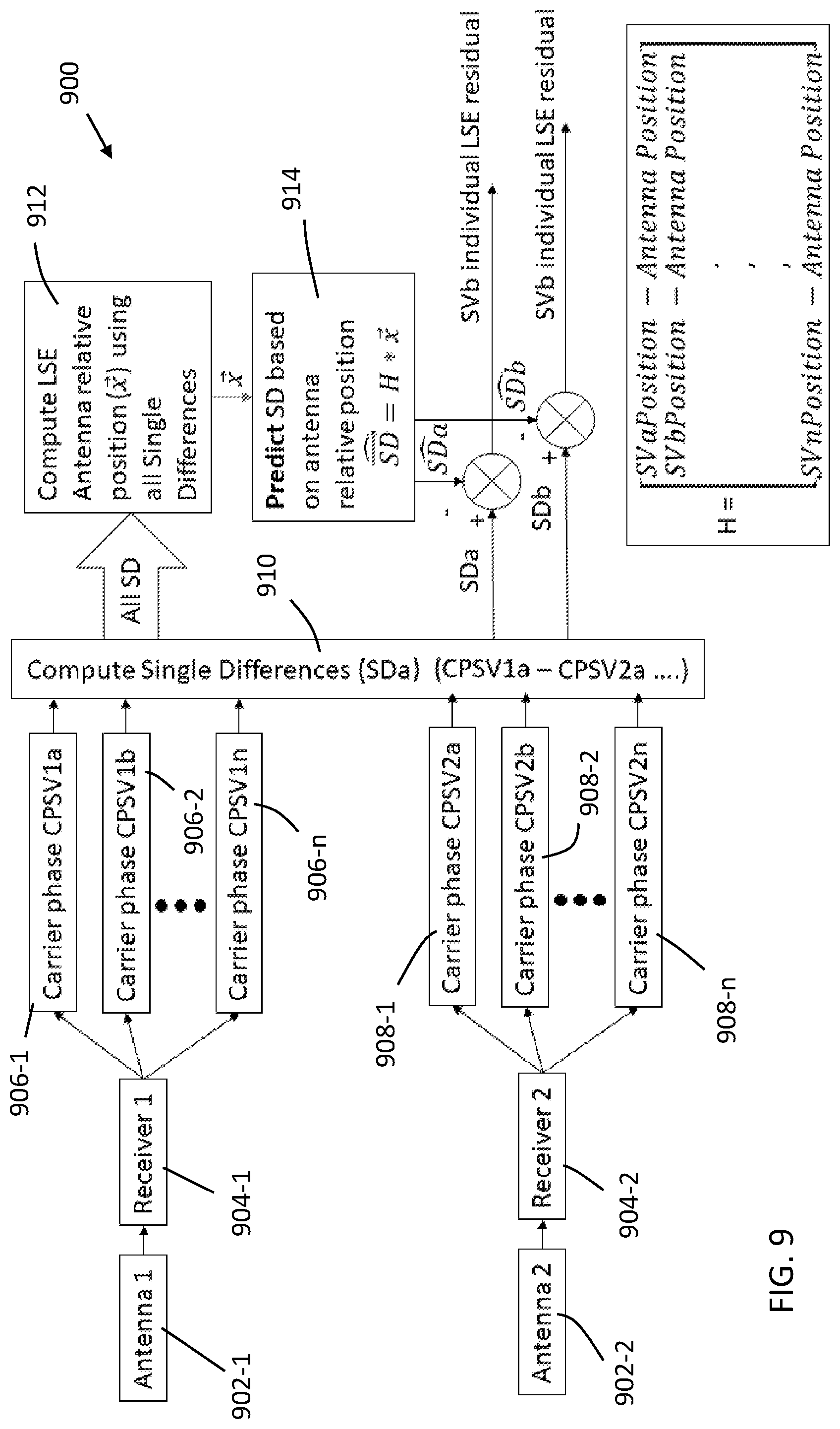
When navigation moves from indoor to outdoor environments, antenna geometry becomes critical for maintaining accuracy. Terra Drone (a Japanese company specializing in industrial drone services and autonomous flight systems) developed an annular GNSS antenna ring that addresses this challenge by distributing multiple low-cost receivers around the UAV's center in a circular pattern.
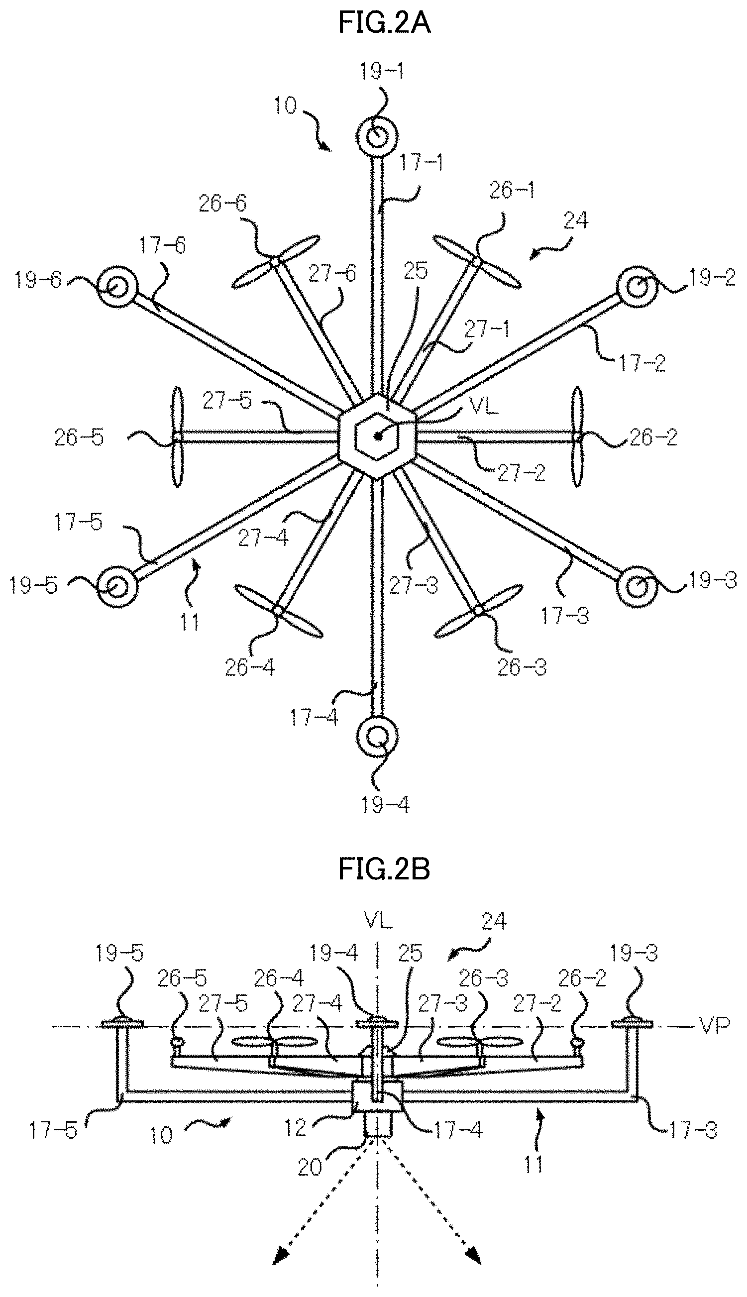
This ring configuration creates long carrier-phase baselines between antennas, providing enough geometric separation to resolve both precise position and full three-axis attitude information. The system operates independently of inertial sensors, reducing the aircraft's size, weight, and power requirements while maintaining clear sky visibility for satellite reception. The distributed antenna placement ensures that satellite signals remain unobstructed regardless of the aircraft's orientation during flight.
5.2. Time-Multiplexed Single-Receiver Solutions
Multiple antennas provide better accuracy, but the cost increases with each additional GNSS receiver required. Sony developed a time-multiplexed single-receiver compass that solves this problem by connecting several antennas to a single receiver through a fast RF switch. The system rapidly cycles between antennas, carefully tracking the timing delays introduced by each switch operation.
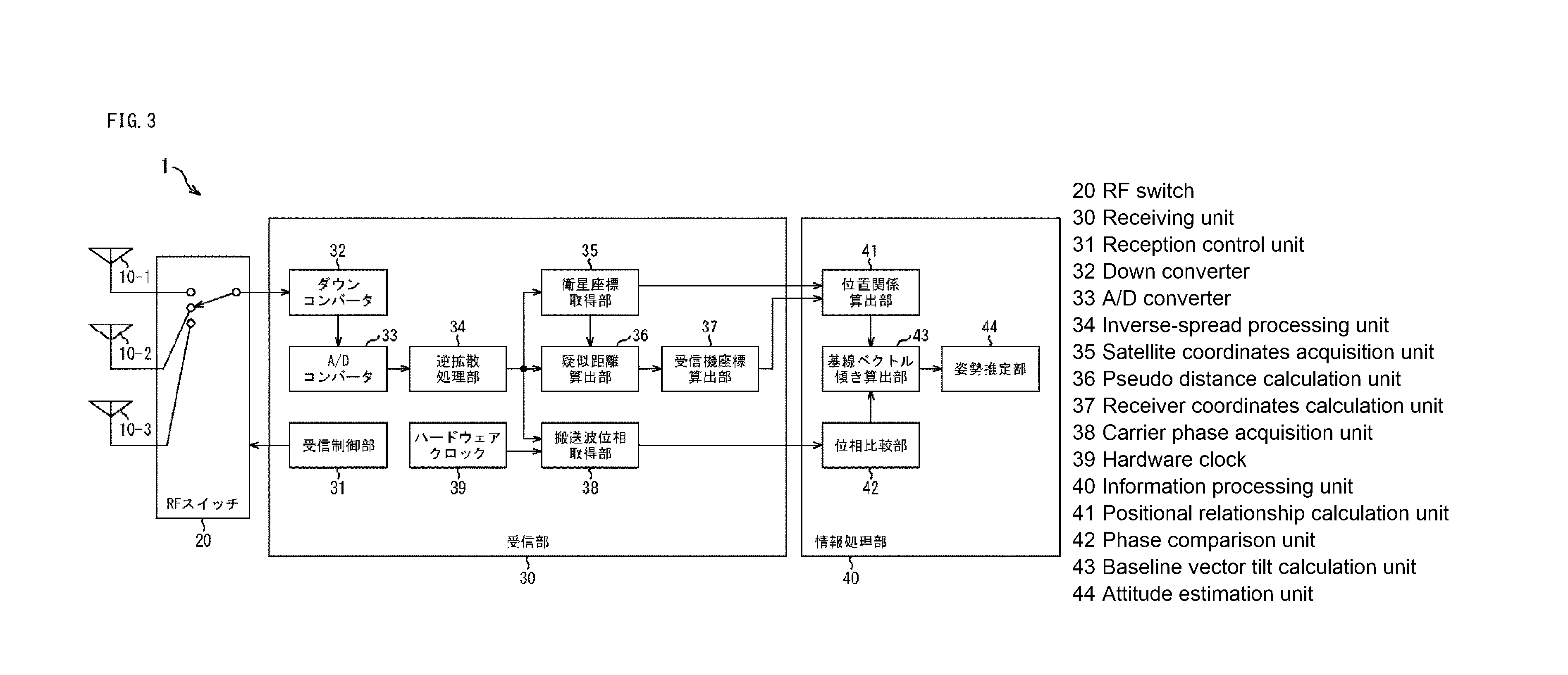
By precisely accounting for these switching delays, the navigation system can reconstruct carrier-phase differences between antennas as if they were all being sampled at the same moment. This approach gives small UAVs and nanosatellites access to absolute attitude determination without requiring multiple expensive receivers or relying on gravity-based orientation cues from accelerometers.
5.3. Inertial-Aided Doppler Compensation
Long baselines between GNSS antennas can significantly improve positioning accuracy, but only if the receiver can maintain phase lock while the aircraft is moving. During flight, Doppler shifts from aircraft motion can cause tracking loops to lose lock on satellite signals, especially in challenging environments with weak signals or interference.
u-blox (a Swiss company specializing in positioning and wireless communication semiconductors for automotive, industrial, and consumer markets) developed an inertial-aided Doppler wipe-off engine that addresses this challenge. The system works by feeding IMU-derived velocity estimates directly into the GNSS receiver's tracking loops. These inertial measurements provide accurate predictions of the expected Doppler shift, allowing the receiver to compensate for aircraft motion in real-time.
This approach enables much longer coherent integration times, which increases the receiver's sensitivity to weak satellite signals. The improved sensitivity reduces the likelihood of losing carrier phase lock during maneuvers and significantly speeds up the time required to achieve first fix when operating in urban canyon environments where satellite signals are partially blocked by buildings.
5.4. Multi-Layer Validation Systems
Improved sensitivity alone is not enough - the system must also verify that its calculated position solution is actually correct. Honeywell (a U.S. technology leader providing solutions in aerospace, automation, energy, and sustainability to make the world smarter, safer, and more sustainable) developed a multi-layer integer-ambiguity-screened heading system that addresses this challenge through multiple validation layers.
The system works by applying residual checks at two different time scales: instantaneous measurements and sliding-window averages over longer periods. It then separates different satellite constellation subsets (GPS, GLONASS, Galileo) and cross-validates the solutions between them. Only integer solutions that pass all these screening tests are accepted for navigation use. This rigorous validation process delivers magnetometer-free heading determination that meets the strict reliability standards required for aviation applications, ensuring that pilots can trust the system even in challenging flight conditions.
5.5. Adaptive Multi-Mode Processing
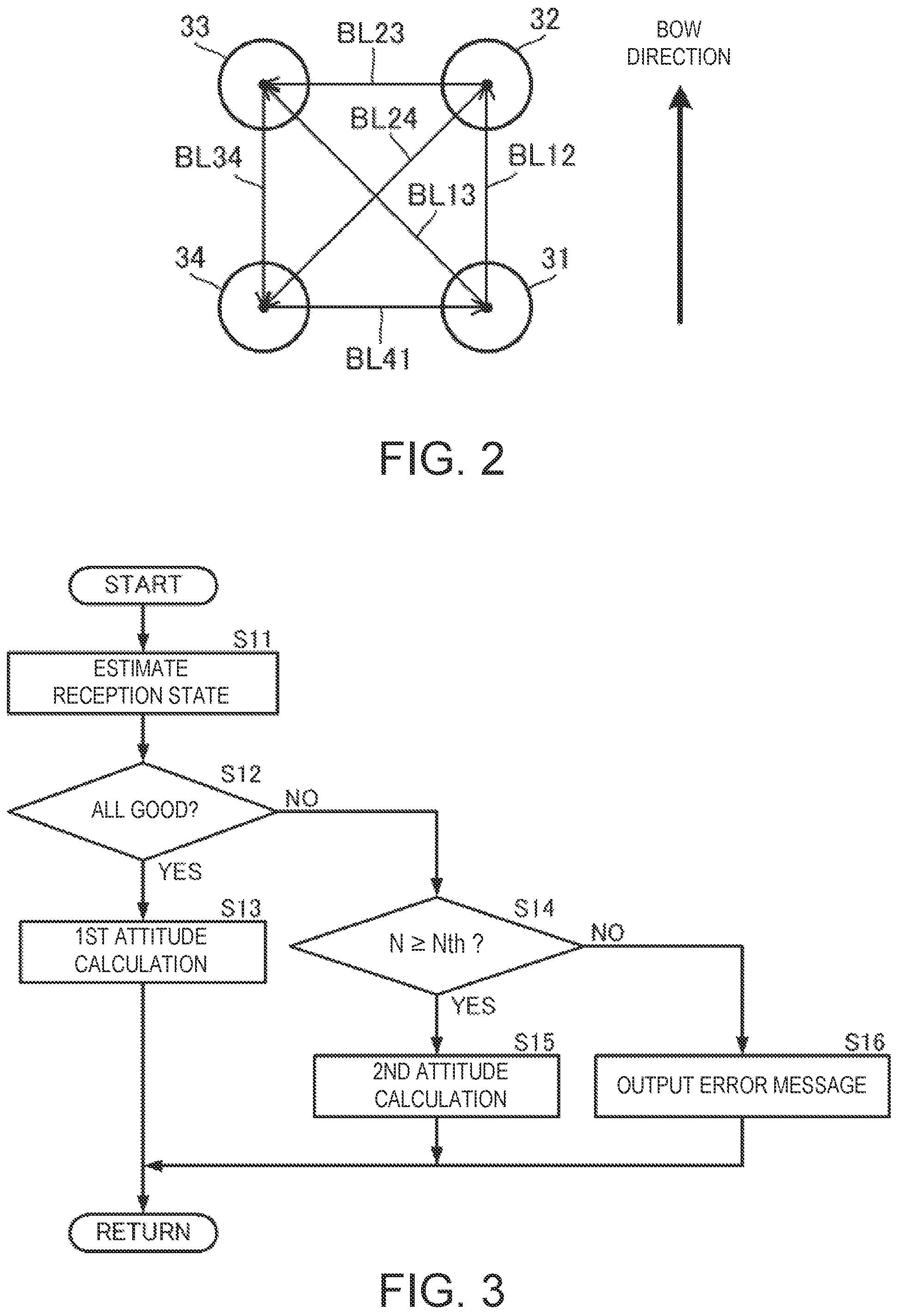
Furuno Electric (a Japanese marine electronics company specializing in radar, sonar, and GPS navigation systems for commercial and recreational vessels) developed an adaptive multi-mode attitude solver that ensures continuous attitude determination even when individual antennas experience signal degradation. The system continuously monitors the quality of data from each antenna in the array and dynamically selects the most appropriate processing algorithm based on current conditions.
Graceful Performance Degradation
When all antennas receive strong, clean signals, the system operates in its highest-accuracy four-antenna carrier-phase mode. However, as signal conditions deteriorate due to building shadows or electromagnetic interference, the system gracefully transitions to three-antenna processing, maintaining reliable attitude output with only slightly reduced precision. In the most challenging environments where only one antenna maintains adequate signal quality, the system seamlessly switches to a hybrid mode that combines single-antenna GNSS data with IMU measurements to preserve attitude continuity throughout the mission.
6. Integrity Management and Anti-Spoofing for Hybrid INS/GNSS
High-fidelity GNSS systems can deliver exceptional accuracy, but that precision becomes meaningless without proper safeguards against signal degradation and interference.
6.1. Dual-Path Certified Navigation Architecture
Safran Electronics & Defense developed a dual-path certified navigation architecture that addresses this challenge by running two parallel estimation processes simultaneously.
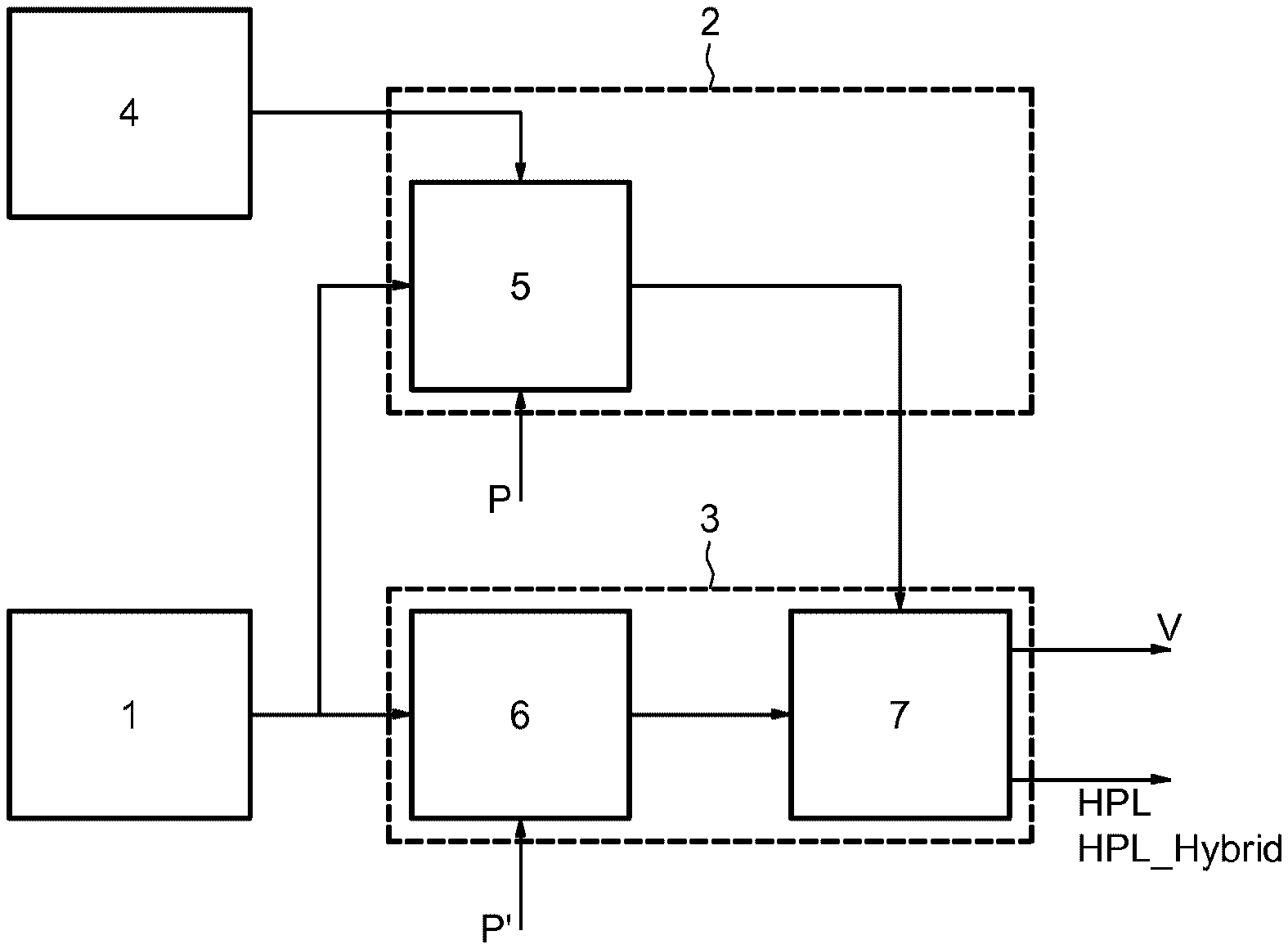
The first processing chain operates as a hybrid filter that combines GNSS and inertial data to produce the most accurate possible estimates of position, velocity, and attitude. Meanwhile, the second chain focuses on reliability rather than precision - it analyzes the uncertainty in the navigation solution and calculates horizontal, vertical, and attitude protection limits based on the system's covariance matrices.
This dual-path approach ensures that the flight control system always receives position and attitude data with guaranteed accuracy bounds. Even when GNSS signals are lost, degraded, or deliberately spoofed, the protection limits automatically adjust to reflect the reduced confidence in the navigation solution. The flight stack can then make informed decisions about mission continuation based on these mathematically rigorous uncertainty bounds rather than relying on potentially corrupted position estimates.
6.2. Attitude Protection Radius for Payload Operations
Building on these protection concepts, Thales (a French multinational corporation specializing in aerospace, defense, and transportation technologies) developed an attitude protection radius system that addresses the challenge of maintaining pointing accuracy for payload operations. When a drone carries cameras, sensors, or other equipment that must aim at specific targets, small attitude errors can cause significant pointing mistakes.
Single Scalar Protection Value
The system works by calculating a single protection radius value that bounds the maximum possible error in roll, pitch, and yaw angles. This calculation combines three key factors: how GNSS measurement errors transfer into attitude uncertainties, the current horizontal protection limits from the GNSS receiver, and a constant that accounts for drift and noise in the inertial sensors.
The flight controller receives this single scalar radius value, which guarantees that the aircraft's true attitude lies somewhere within the calculated envelope. This approach gives payload operators confidence that their pointing accuracy remains within acceptable limits, even when navigation uncertainties fluctuate during flight operations.
6.3. Multi-Domain GNSS Spoofing Detection
Even the most sophisticated error detection systems become useless if the GNSS signals themselves are deliberately falsified. Honeywell developed a multi-domain GNSS spoofing detector that addresses this threat by monitoring multiple independent indicators within the navigation filter itself.
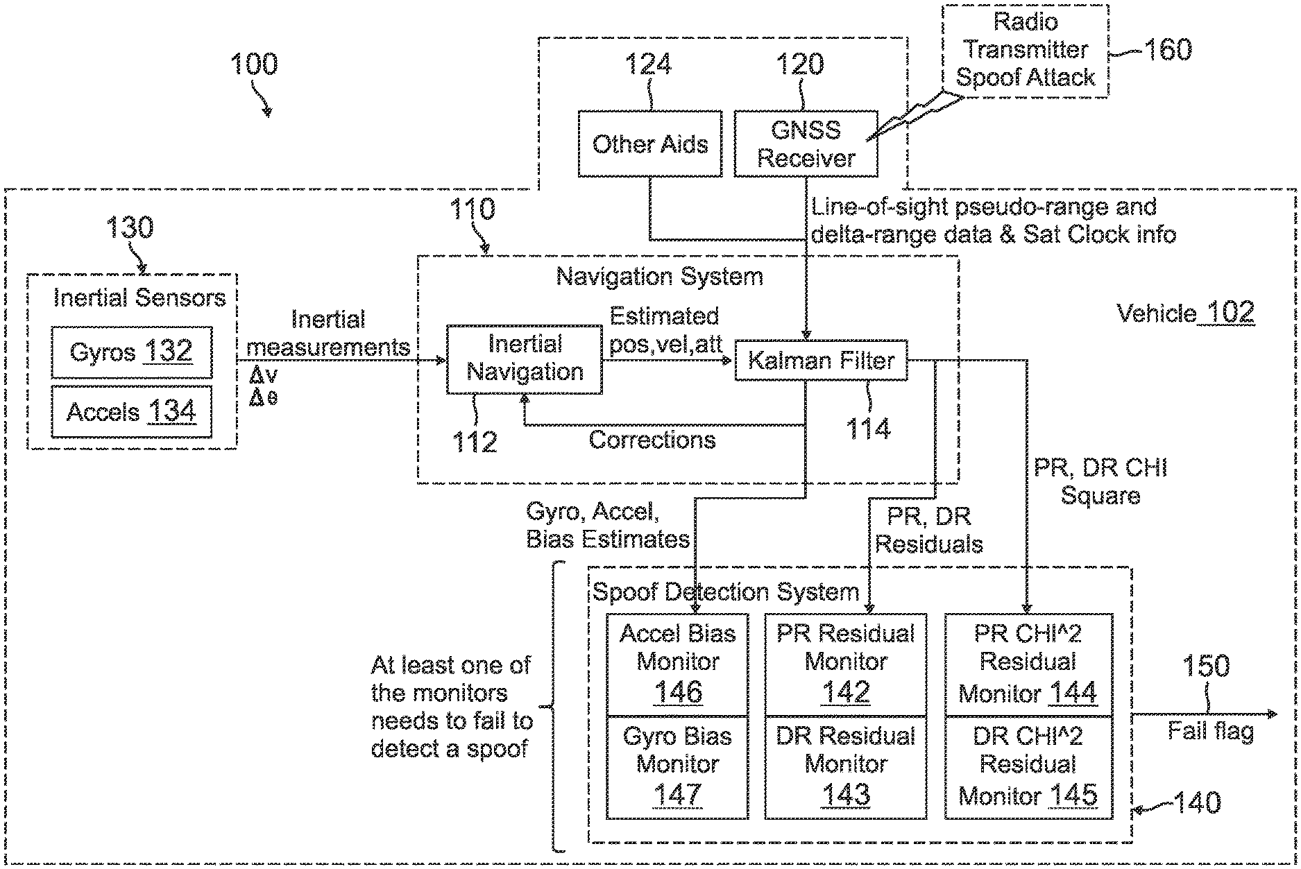
Triple-Metric Monitoring System
The system continuously tracks three key metrics: range residuals that measure how well satellite measurements match expected values, chi-square statistics that detect unusual patterns in the measurement data, and estimated IMU bias drift rates that reveal when inertial sensors are being forced to compensate for false GNSS inputs. Each metric operates with its own calibrated threshold based on normal flight conditions.
Real-Time Response to Electronic Attacks
When spoofing occurs, these indicators typically change simultaneously across multiple domains, creating a distinctive signature that the detector can recognize within milliseconds. Once spoofing is confirmed, the system immediately isolates the corrupted GNSS data and switches to pure inertial navigation mode. The aircraft continues operating on IMU data alone until authentic satellite signals are restored, ensuring that flight operations remain safe even under deliberate electronic attack.
7. Geophysical, Map and Signals-of-Opportunity Aiding
When satellites disappear or integrity metrics fail, geophysical aids can keep navigation systems operating within acceptable bounds.
7.1 Altitude-Aware Multi-Sensor Integration
Atlantic Inertial Systems developed an altitude-aware sensor-weighting Kalman filter that addresses this challenge by intelligently combining inertial data with terrain-referenced position fixes and star-tracker sightings.
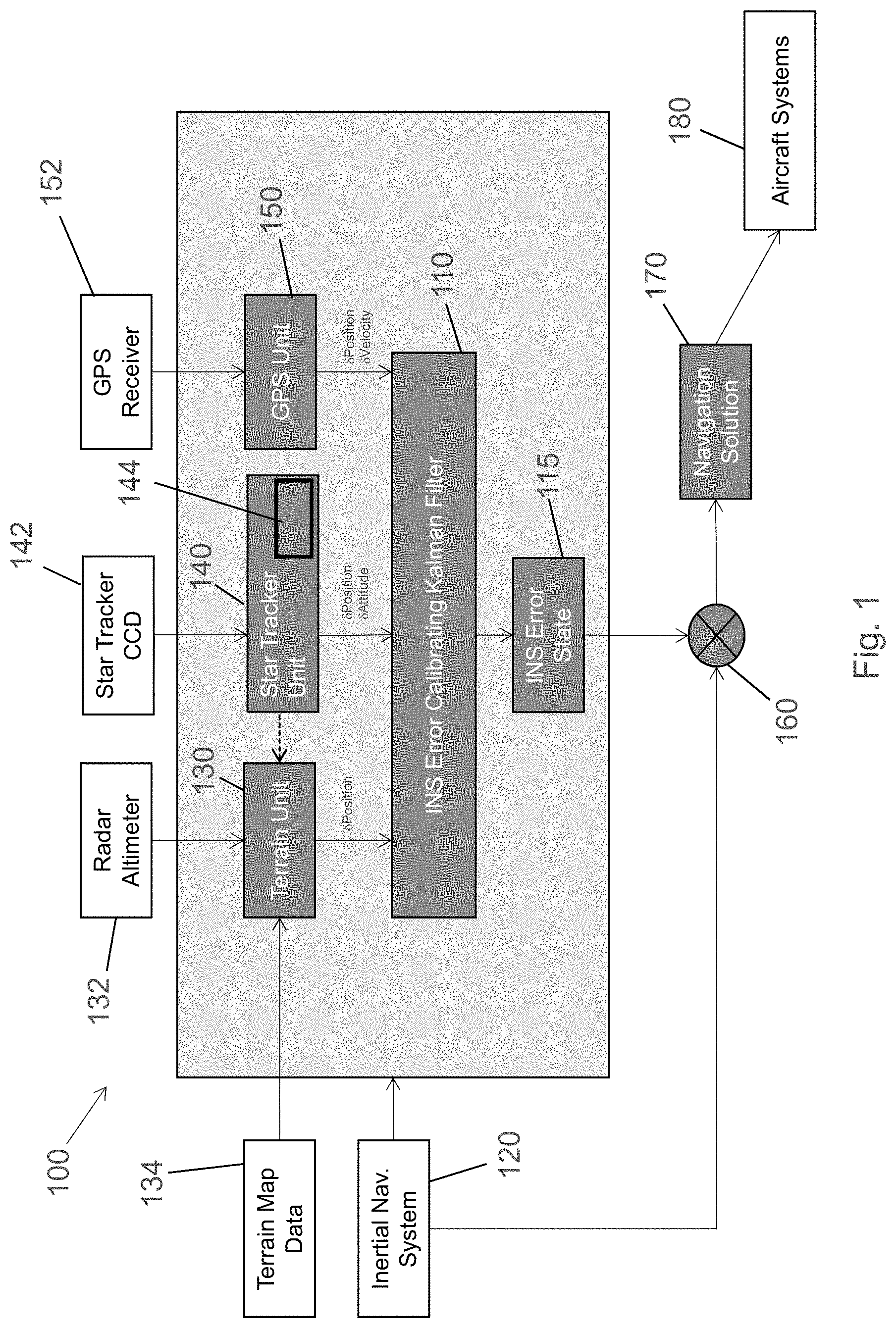
The system works by dynamically adjusting the trust it places in different sensor types based on current flight conditions. At high altitudes, the filter reduces reliance on terrain-matching systems because radar footprints become too large and blurry to provide accurate position references. Conversely, during low-level flight in bright sunlight, the system throttles back the star tracker since celestial navigation becomes unreliable when stars are not clearly visible.
Seamless Sensor Transitions
The key innovation lies in how these sensor transitions occur. Rather than switching abruptly between different navigation modes, the system creates deliberate overlap periods where multiple sensors contribute simultaneously. This approach prevents navigation gaps that could occur during mode switches, ensuring seamless position and attitude estimates even when primary navigation aids become unavailable.
7.2 Computationally Efficient Terrain Matching
Subaru (a Japanese automaker known for all-wheel-drive vehicles and boxer engines) developed a reference-point constrained geo-/celestial matcher that solves the computational challenge of full-map matching on embedded processors. The system works by limiting its search area to only the region suggested by the current INS state estimate, rather than attempting to match against an entire global database.
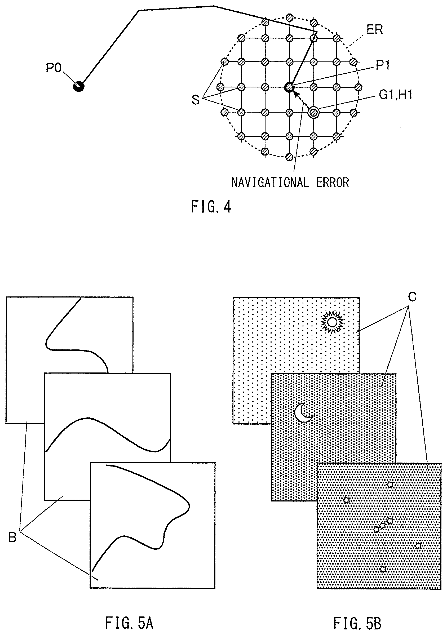
The algorithm divides this constrained search space into discrete segments and generates synthetic reference scenes for each candidate location. It then compares the aircraft's actual camera or sensor imagery only against these pre-calculated candidates. This targeted approach makes continuous GPS-free navigation updates practical without overwhelming the onboard processor, enabling terrain-referenced navigation even on lightweight UAV platforms with limited computational resources.
7.3 Gravity-Based Navigation Systems
Terrain matching provides useful position references, but gravity anomaly measurements can correct horizontal drift more effectively than visual landmarks.
Strapdown Gravimetric Architecture
Honeywell developed a strapdown gravimetric aiding architecture that addresses this challenge by embedding a vertical accelerometer within the navigation system. This accelerometer serves a dual purpose: it functions as both a standard motion sensor and a precision gravimeter that measures local gravitational field variations.
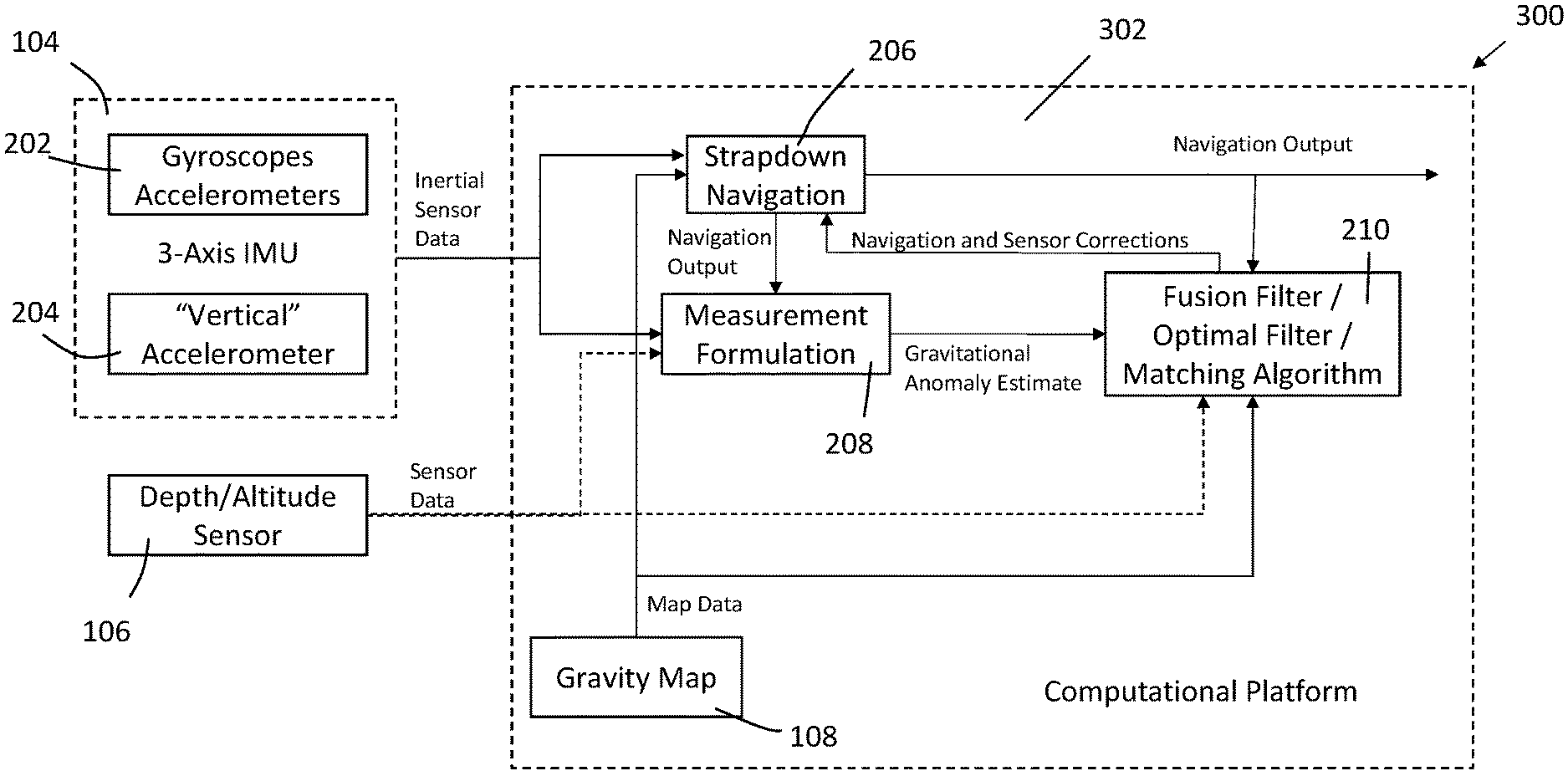
The system works by cross-referencing real-time gravity measurements against a pre-loaded gravity anomaly map stored in the aircraft's memory. When the measured gravitational field matches a specific location on the map, the navigation system receives a position fix that can correct accumulated INS drift.
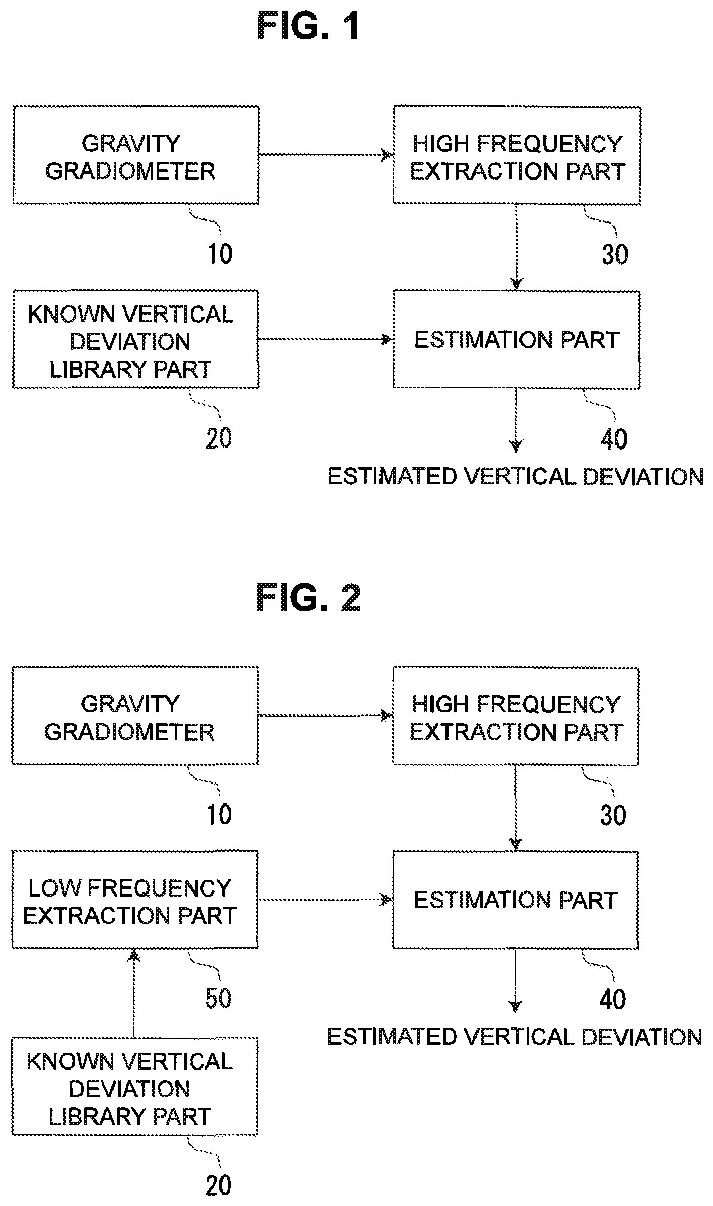
Dual-Domain Vertical Deflection Fusion
To enhance this approach further, the dual-domain vertical deflection fusion technique combines coarse long-wavelength gravity data from regional maps with high-frequency measurements from a low-cost gravity gradiometer mounted on the aircraft. This dual-domain fusion provides both broad-area position references and fine-scale corrections, enabling continuous navigation updates even in areas where terrain features are too uniform for visual matching systems.
7.4 Plumb-Line Deviation Estimation
Real-time gravimetry feeds into plumb-line estimation, which measures how local gravity variations cause a plumb line to deviate from true vertical. Japan Aviation Electronics (a Japanese aerospace company specializing in avionics, inertial navigation systems, and flight control equipment) developed a plumb-line deviation Kalman estimator that treats these deviations as explicit states within the navigation filter.
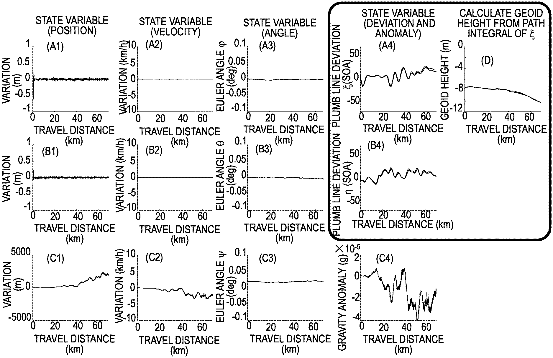
The system works by mounting a survey-grade IMU to the aircraft platform and continuously measuring how the local gravitational field differs from the theoretical Earth model. These measurements reveal the precise direction of "down" at each location, providing an independent vertical reference that doesn't rely on satellite signals or visual landmarks. The Kalman filter incorporates these plumb-line measurements alongside standard inertial data, delivering centimeter-level vertical positioning accuracy that traditionally required labor-intensive ground surveying and leveling operations.
7.5 Signals-of-Opportunity Navigation
When traditional navigation aids like maps and star trackers become unavailable, civilian radio frequency signals can serve as a final backup for position determination.
Multi-Source Signal Processing
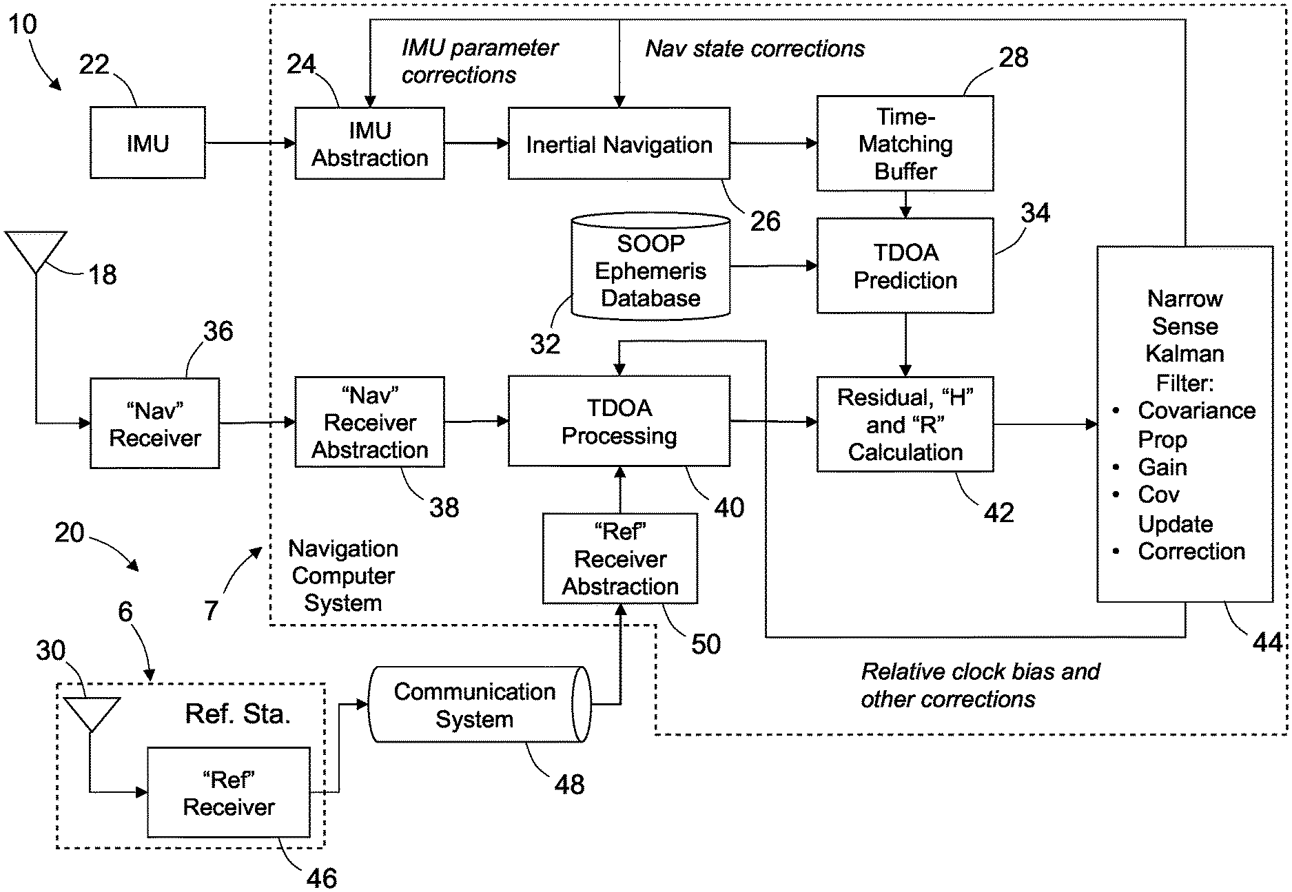
Raytheon Systems (a British subsidiary of the U.S. defense contractor, specializing in radar systems and electronic warfare technology) developed a SoO-IMU multilateration engine that addresses this challenge by listening to signals from satellite constellations like Starlink and Iridium, as well as terrestrial broadcast transmissions.
The system works by estimating either range or Doppler shift measurements to individual transmitters, then fusing this information with standard inertial navigation data. This approach transforms existing communication signals into navigation references without requiring any modifications to the transmitting infrastructure. The accuracy of this technique improves significantly when multiple ground-based receivers contribute data to a centralized database that tracks transmitter locations and timing.
Network-Assisted Ephemeris Services
This concept is formalized in the network-assisted SOOP ephemeris service, which creates a crowd-sourced system where distributed receivers continuously monitor signal characteristics and feed this information to a backend service. The service then provides updated ephemeris data - precise information about transmitter positions and timing - that enables individual aircraft to achieve better positioning accuracy using signals of opportunity.
8. Cooperative Ranging and Formation Navigation
When multiple vehicles operate together, peer-to-peer ranging can distribute navigation accuracy across the entire formation. Each aircraft becomes both a navigation aid and a beneficiary for its neighbors, creating a self-supporting network that's more resilient than any individual platform.
8.1. Two-Way Timing and Ranging for Cooperative Navigation
Rosemount Aerospace (a U.S. company specializing in aircraft sensors, probes, and ice protection systems for commercial and military aviation) developed a two-way timing and ranging datalink that enables this cooperative approach. The system allows each aircraft to measure precise distances to selected peers while simultaneously exchanging state estimates and their associated uncertainty values.
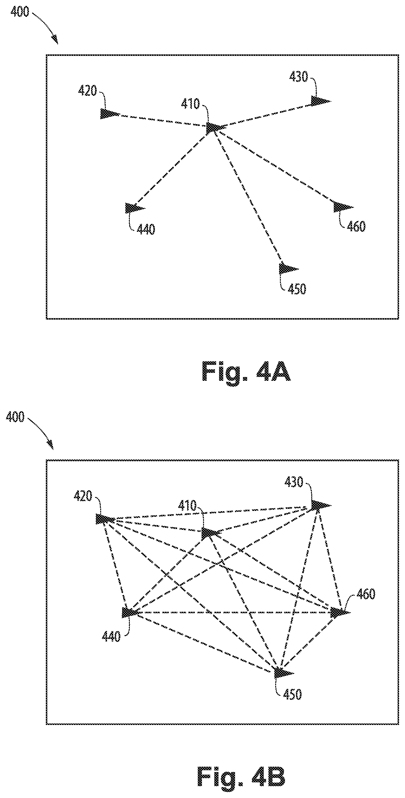
The ranging process works by having aircraft exchange precisely timed radio signals, measuring the round-trip delay to calculate inter-vehicle distances. Concurrently, each platform shares its current position estimate along with covariance data that indicates how confident it is in that estimate.
The navigation system then fuses these inter-vehicle range measurements with local INS data, using the peer information to correct drift before it can corrupt the formation's overall accuracy. This cooperative approach means that even if individual aircraft experience temporary navigation degradation, the formation as a whole maintains its positioning integrity.
8.2. Distributed Spring-Force Formation Control
While shared ranging stabilizes drift, real-time coordination is needed to keep the swarm coherent as a unified formation. Rosemount Aerospace developed a fully distributed spring-force formation algorithm that addresses this challenge by treating each aircraft as a node in a virtual spring network.
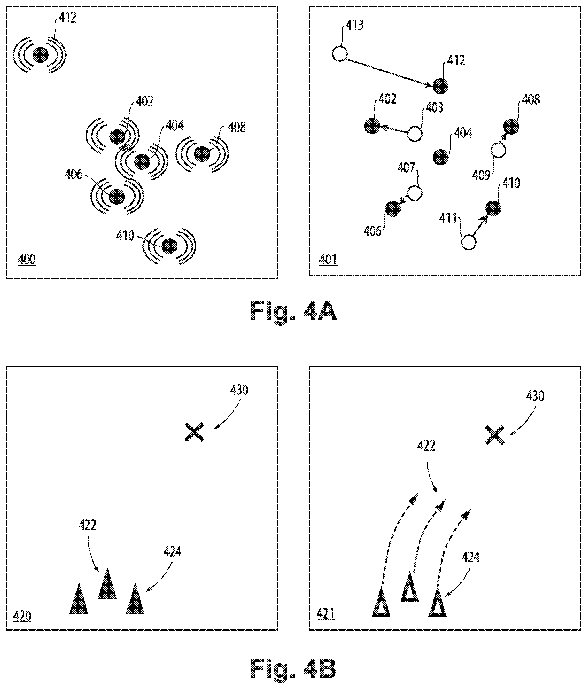
Each aircraft continuously broadcasts its current state information to all other members of the formation. Individual platforms then calculate the distance separations to their neighbors and apply virtual spring forces that push or pull the aircraft toward its desired position within the overall geometry. These spring forces create a self-organizing system that naturally drives the entire formation toward its target configuration without requiring any central coordination.
Resilient Architecture Without Central Control
This distributed approach eliminates single points of failure that could compromise the entire mission. No vulnerable lead platform or high-bandwidth command channel is required - each aircraft makes its own navigation decisions based on the peer information it receives, creating a resilient formation that can maintain coherence even if individual platforms experience communication failures or navigation degradation.
8.3. RF-Silent Cooperative Navigation for Stealth Operations
Some missions cannot tolerate radio emissions that might reveal the aircraft's presence to hostile forces. Rockwell Collins developed a cooperative passive navigation architecture that addresses this challenge by pairing two aircraft with complementary positioning capabilities.
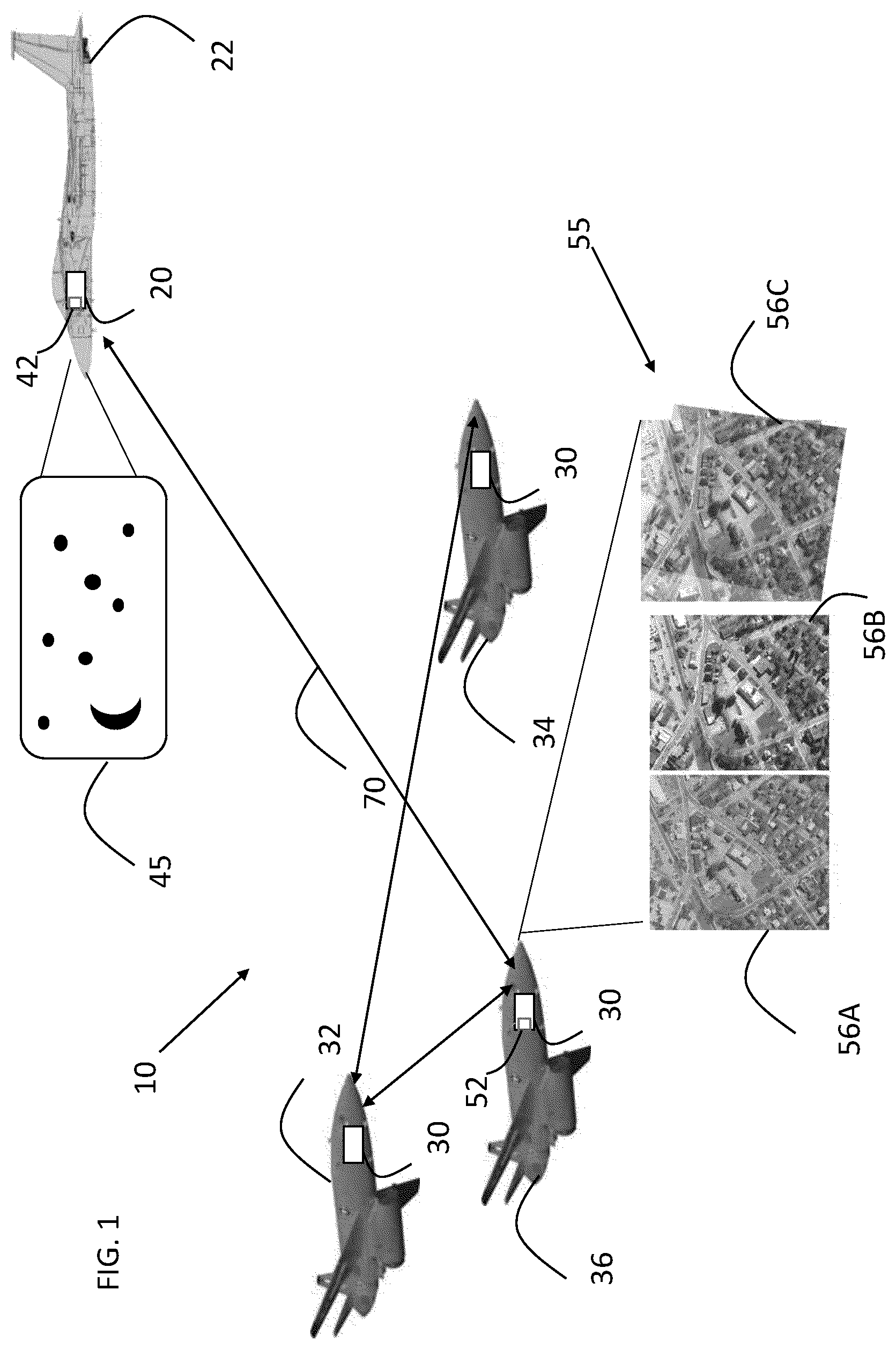
The architecture equips one aircraft with a celestial navigation tracker optimized for high-altitude operations, while a second platform carries terrain-matching vision systems designed for low-level flight. Each aircraft processes its sensor data locally to derive position estimates, then shares only these calculated navigation states with its partner through short-range, low-power data links.
Complementary Sensor Fusion for Silent Operations
This cooperative approach allows both platforms to maintain precise relative positioning without transmitting any signals that could be detected by external monitoring systems. The high-altitude platform provides stable absolute position references through star sightings, while the low-altitude aircraft contributes fine-scale position updates through terrain correlation. Together, they create a self-contained navigation network that remains completely RF silent to the outside world while delivering the positioning accuracy needed for coordinated mission execution.
9. Model-Aided Fusion for High-Dynamics and Load-Carrying Missions
Cooperative cues stabilize the swarm, but individual vehicles still face violent maneuvers and shifting payloads that can destabilize flight operations. When a slung load changes the aircraft's center of mass every second, traditional control systems struggle to maintain stable flight.
9.1 Multi-Sensor Load Stabilization Systems
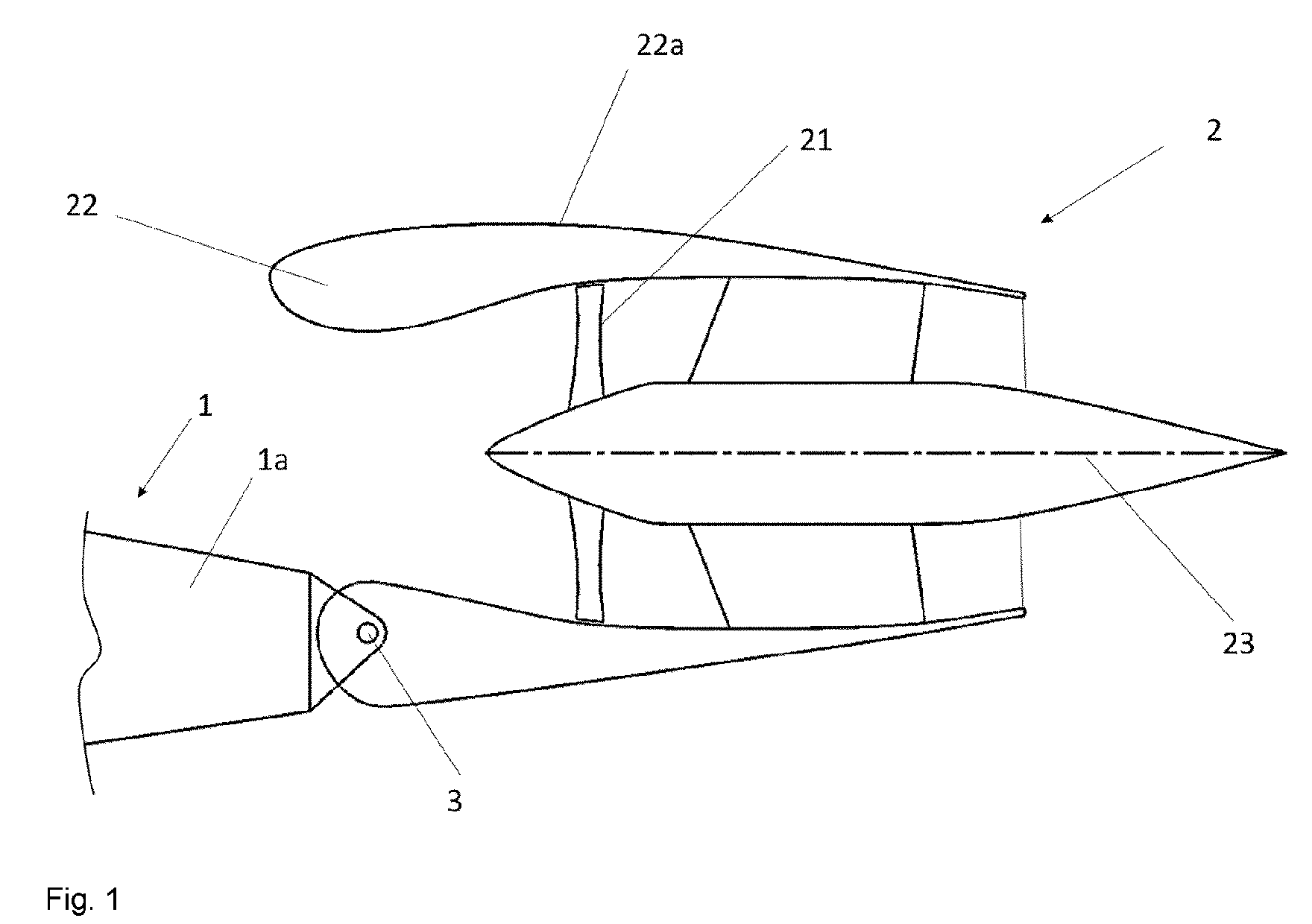
Vita Inclinata (a U.S. company specializing in load stabilization systems for helicopters and drones) developed a Suspended-Equipment Control System that addresses this challenge by combining multiple sensor types within a single integrated control framework. The system blends data from IMUs mounted on both the airframe and the suspended load, cable force sensors that measure tension variations, LiDAR for spatial awareness, cameras for visual feedback, and GPS for absolute positioning references.

All of this sensor data feeds into an augmented nonlinear Kalman filter that estimates the dynamic state of both the aircraft and its suspended cargo in real-time. The control system then coordinates multiple actuators simultaneously: fuzzy-tuned PID loops manage basic flight control, neural network compensators adapt to changing load characteristics, and rope-hoist mechanisms actively adjust cable length to counteract pendular motion and reorient the package as needed. This comprehensive approach enables stable flight operations even when carrying dynamic loads that would otherwise make the aircraft uncontrollable.
9.2 Thrust-Based Failure Mitigation
Lilium (a German aerospace company developing electric vertical takeoff and landing aircraft for urban air mobility) developed a thrust-based flutter suppression loop that addresses the challenge of propulsion unit failures triggering destructive resonance. When individual motors or propellers fail, the resulting imbalance can cause dangerous vibrations that threaten the entire aircraft structure.
Rather than simply reducing power when a failure occurs, the system continuously monitors for signs of structural resonance and dynamically adjusts both the magnitude and direction of thrust from the remaining functional propulsion units. The control system actively modulates the thrust vector to rebalance the aircraft, dampen harmful vibrations, and counteract any structural deformation that might develop. This approach eliminates the need for additional hardware like mechanical dampers or backup actuators, relying instead on intelligent coordination of the existing propulsion system to maintain safe flight operations even after component failures.
9.3 Numerical Stability in Resource-Constrained Environments
Even the most sophisticated control systems become ineffective if the underlying navigation estimator suffers from numerical instability. Small embedded processors with limited computational resources can struggle with the matrix operations required for advanced Kalman filtering, especially when dealing with ill-conditioned covariance matrices that arise during complex maneuvers.
Bidirectional Processing Architecture
ARMINES (a French research association specializing in industrial processes and methods development) developed a forward-backward stochastic-cloned Kalman filter that addresses this challenge through a two-stage processing approach. The system first linearizes the navigation model within a sliding time window, then propagates the aircraft's state forward using standard inertial measurements. Once the forward propagation is complete, the filter runs a backward pass that applies corrections derived from the forward estimates.
This bidirectional approach prevents the numerical problems that can occur when 32-bit microcontrollers attempt to invert poorly conditioned matrices during real-time operations. By separating the forward prediction step from the backward correction phase, the algorithm maintains numerical stability even when processing challenging flight dynamics or sensor configurations that would cause traditional Kalman filters to diverge.
9.4 Magnetometer-Free Heading Determination
Yaw determination becomes problematic in magnetically contaminated environments where traditional magnetometers fail to provide reliable heading references. Steel structures, electrical systems, and electromagnetic interference can cause compass readings to drift significantly from true magnetic north.
Sony developed a non-holonomic constraint yaw resolver that addresses this challenge without relying on magnetic field measurements. The system works by systematically testing different candidate heading angles and evaluating how well each one satisfies the aircraft's motion constraints.
For each potential yaw angle, the algorithm transforms accelerometer measurements from the aircraft's body frame into the navigation frame using that candidate heading. It then checks whether the resulting velocity estimates are physically consistent with the aircraft's known motion characteristics - for example, whether a fixed-wing aircraft is moving primarily in its forward direction rather than sliding sideways through the air.
The heading angle that produces the most consistent motion profile is selected as the correct yaw reference. This approach enables the navigation system to determine heading accurately while the aircraft is in motion, eliminating the need for stationary alignment periods or external reference points that might not be available in operational environments.
10. Reconfigurable Autonomy Hardware with Redundant Sensor Networks
All these algorithms must live on hardware that survives faults and reconfiguration. Conventional flight systems scatter critical components like flight-control processors, GNSS receivers, altimeters, and radar units across multiple separate line-replaceable units throughout the aircraft. This distributed approach creates several problems: extensive wiring harnesses that add weight and failure points, communication latencies between distant components, and higher overall power consumption.
10.1 Single-Board Autonomy Integration
Joby Aero (a U.S. electric aviation company developing electric vertical takeoff and landing aircraft for urban air mobility) developed a reconfigurable single-board autonomy computer that addresses these challenges by consolidating the entire navigation and flight control stack onto a single printed circuit board. The integrated design combines system-on-chip processors, data storage, and three different types of sensors within one compact package.
Eliminating Traditional Communication Bottlenecks
This co-location approach eliminates the bandwidth-hungry backplane connections that traditionally link separate avionics boxes together. More importantly, it enables real-time triple-redundant localization processing where multiple sensor streams can be fused with microsecond-level timing precision.
The system architecture allows identical boards to communicate and vote on which unit should serve as the primary controller for surveillance, guidance, and flight control functions. Hot standby boards remain ready to take over within microseconds if the primary unit experiences any failure, ensuring continuous flight operations even during hardware malfunctions.
10.2 Hierarchical Sensor Fusion for Positional Integrity
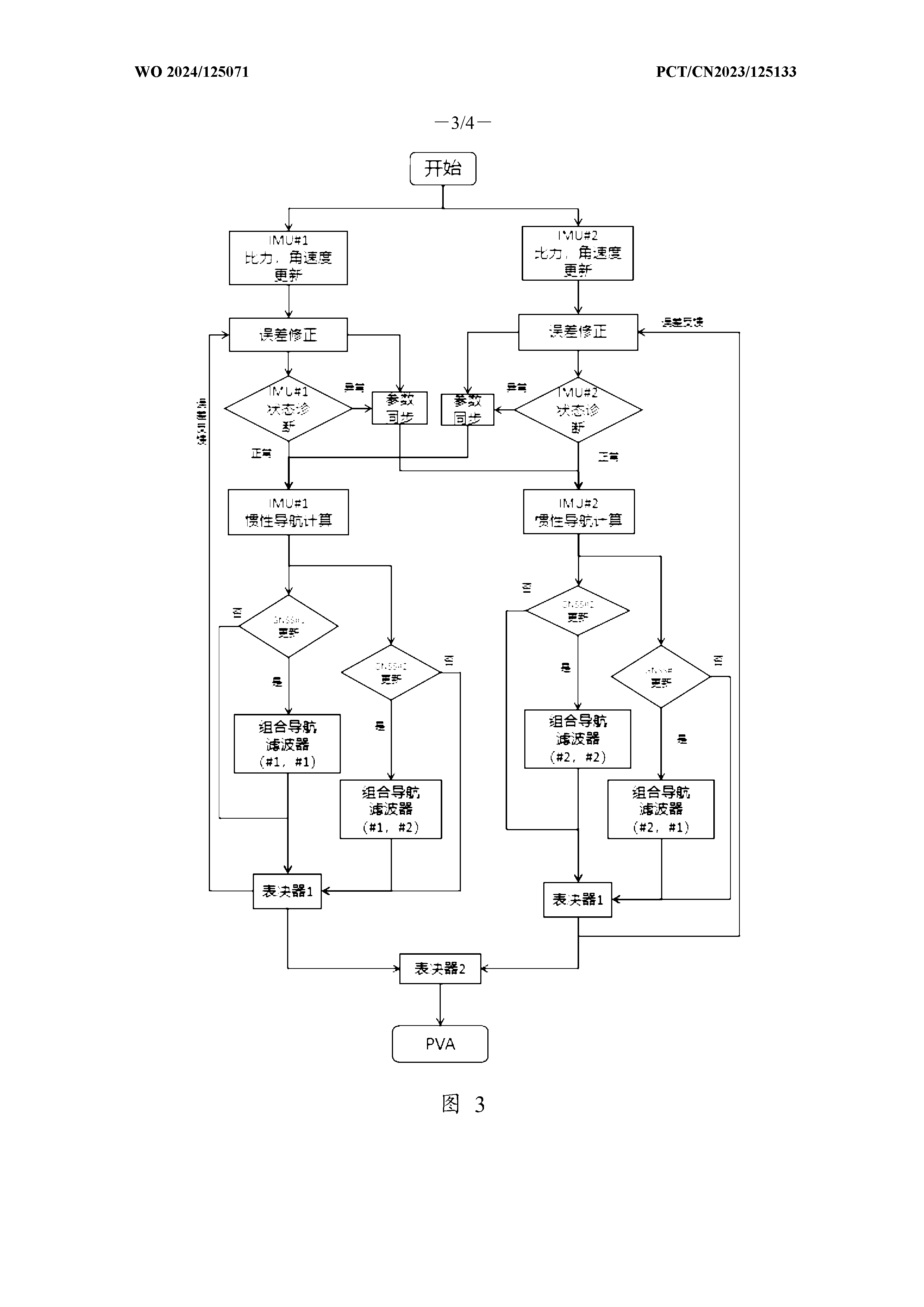
Board-level integration reduces wiring complexity, but positional integrity still requires multiple independent IMUs and GNSS receivers operating within that consolidated hardware. Chinese researchers developed a hierarchical voting fusion algorithm that enables several INS/GNSS pairs to operate in parallel on the same board.
Multi-Level Decision Making Process
The system works by running pairwise error comparisons between different sensor combinations, automatically selecting the candidate with the lowest error metrics at each decision point. A top-level voting mechanism then evaluates all the pairwise winners to identify the best overall navigation solution for flight control use.
Rather than discarding the losing estimates, the algorithm recycles this data to help correct sensor drift in the remaining units, maximizing the value extracted from every measurement. A secondary INS unit continuously monitors the health of the primary navigation solution, ready to take over if the main system experiences degradation.
This hierarchical approach maintains update rates near 200 Hz while ensuring that absolute positioning accuracy persists long after any individual sensor experiences failure, providing the redundancy needed for safe autonomous operations.
Get Full Report
Access our comprehensive collection of 89 documents related to this technology
