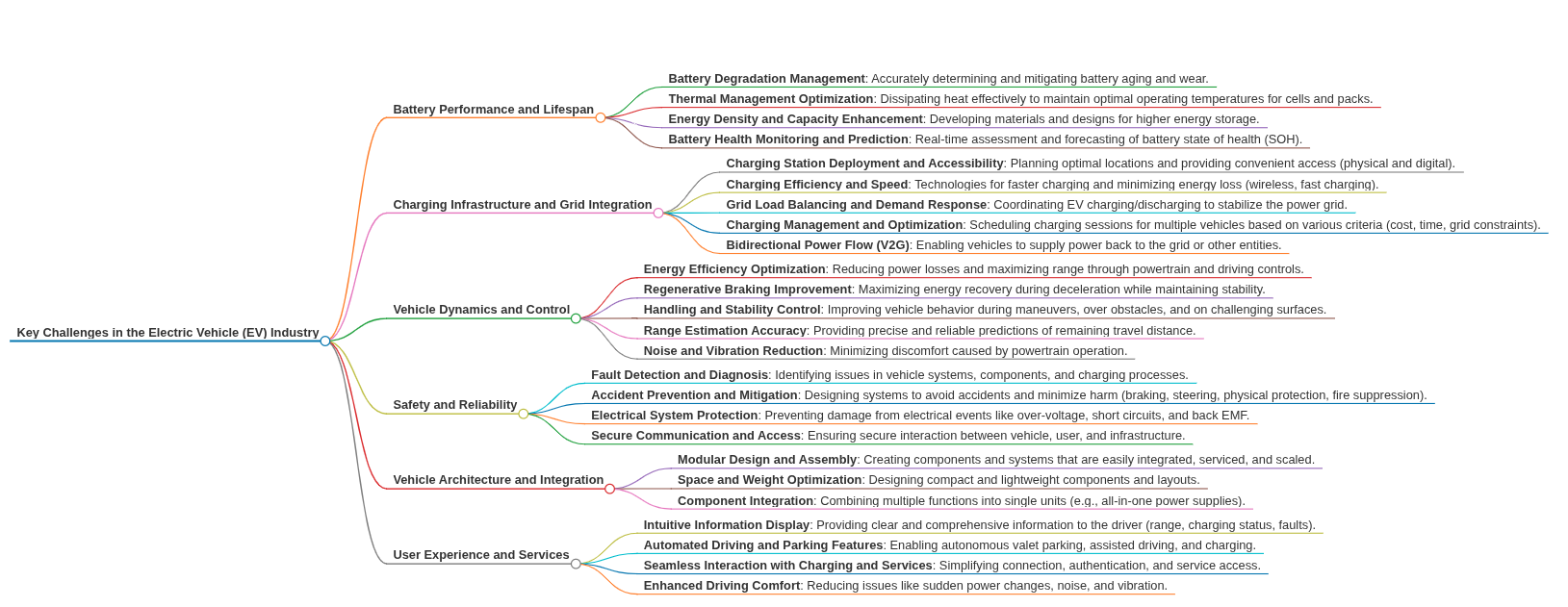
Modular Architecture in EV Battery Systems
Electric vehicle battery packs face mounting complexity in their assembly, with typical designs containing thousands of interconnected cells, thermal management components, and sensor systems. Current manufacturing processes require extensive manual assembly steps, creating bottlenecks that can limit production to 5-10 battery packs per hour in many facilities.
The fundamental challenge lies in designing battery systems that optimize for both manufacturing efficiency and performance while maintaining safety and serviceability across the pack's lifecycle.
This page brings together solutions from recent research—including integrated bus bar designs that eliminate separate connection components, simplified cell-to-module assembly techniques, thermal management innovations, and serviceable pack architectures that enable targeted maintenance. These and other approaches demonstrate how modular design principles are being applied to streamline EV battery production while maintaining robust performance.
TABLE OF CONTENTS
1. Swappable and Removable Battery Module Architectures for Service and Capacity Scaling
Long charging stops and fixed voltage-capacity ratios have historically tied EV design to a single, heavy pack. Several modular inventions now let energy blocks go in and out of the vehicle as easily as luggage. A standardised linear-array pack mounts on chassis rails; mechanical latches and integrated power contacts engage automatically when the unit is pushed home, so drivers can drop mass for city use or add packs before extended trips. Heavy-duty trucks work with modules that carry self-aligning conical terminals. These slide on guide rails and lock with one transverse rod, which means crews can replace a fatigued segment without disturbing the rest of the string.
Granularity can be pushed further. A cassette system described as an independently-scalable cassette architecture decouples capacity from voltage, letting engineers tune each parameter without redrawing the enclosure. Field service then focuses on isolating a weak element, not the whole pack. A removable sub-module carrier with inter-locking cooling channels allows one cassette to slide out while its neighbours stay sealed and temperature-controlled. Where recyclability dominates, a reversible clamping frame replaces welds with elastomer-backed bus plates. Loosening a few bolts relieves pressure so cells come out intact for second-life use. Some modules go tool-less by embedding per-cell electronics and spring contacts; a defective prismatic cell can be lifted clear while an on-board buffer holds the string in balance.
System-level hybrids combine fixed energy with detachable boosters. A drivetrain that follows a multi-path switch architecture accepts a lightweight auxiliary pack; existing traction inverters step voltage between packs, avoiding a separate converter. An EV can also carry a flush-mounted auxiliary power unit whose hot-swappable bricks double as 110 V/240 V generators for external tools. Safety remains in the foreground: each module sits in its own chamber and, if thermal runaway begins, an auto-eject mechanism pushes that module clear of the live bus. Mechanical modularity therefore sets the stage for the electrical and manufacturing techniques discussed next.
2. Integrated Busbar and Electrical Interconnect Designs Eliminating Separate Connectors
Pulling a module in seconds is of little value if technicians still need to remove dozens of busbars. The polymer hard-shell concept in housing-embedded current-collecting rails cures this by moulding continuous rails inside the enclosure. End-face pressure contacts pick up current directly from the cells, removing laser welds, shortening conduction paths, and leaving cavities free for sensors or insulation.
When cells must be fixed instead of merely pressed, a fold-up plate and lead architecture folds three hinged plates around the stack. Thin leads slip between plate layers and touch the cell tabs on closure, while a rigid linker bridges successive leads. No welded joints appear in the current path, weld jigs disappear from the line, and the clamped block resists vibration.
Inter-module links can be deleted as well. The case-integrated inter-module conductor lets one internal busbar pierce the sidewall so it mates with the opposite terminal of the next module when the two shells are pushed together. The string is complete without loose hardware, freeing space for cooling plates in crowded chassis tunnels.
The same idea scales down. A single-end terminal pole brings both polarities to one cap on a cylindrical cell, eliminating orientation errors and shortening the thermal path. In small modules a staggered dual-block arrangement uses a through-board sleeve interconnect: current passes through plated vias in a central PCB so paired prismatic cells plug straight in. Across all designs, the conductor is embedded in parts already needed for containment. Assembly time, weight, and hotspot risk all fall, which informs the manufacturing focus in Section 3.
3. Simplified Cell-to-Pack Assembly Methods and Serviceable Housing Constructions
Fast production and field access often work against each other, yet modern cell-to-pack strategies aim for both. Conventional packs seal under one monolithic lid, forcing removal of the whole tray for minor work. Two complementary housings avoid that detour. First, localized service lids are stamped rectangular doors sealed by reusable gaskets. Positioned just aft of the rear-seat footwell, each door grants access to fuses, BMS boards, or a single module while the pack stays in the vehicle. Second, the torsion-bar peel-off panel bonds the top panel with adhesive then lets service teams detach it by rolling the sheet around an integral torsion bar. Wide flanges and rows of bolts disappear, reclaiming volume for cells.
At cell level, prismatic construction is eased by dividing the tab-to-post adapter. A two-piece side-wall adapter and its split adapting component separate pole-side and tab-side parts. One half is pre-welded outside the cavity; the electrode stack drops through the top opening; a short weld or rivet then links the halves. Takt time drops and the weld area grows, cutting resistance.
Pack assembly compresses further when structural and thermal roles live in the same moulded tray. Integrated resin partition cell beds accept cell blocks without intermediate module frames. The resin controls dielectric clearance and moves heat, so insulation layers and serpentine plates vanish. Dense stacks are locked by a central spreading-force retaining mechanism that pushes groups outward against extruded sidewalls, providing uniform preload and optional coolant flow through hollow springs. Non-rectangular layouts are handled by an irregular cell-to-pack enclosure where cells slide directly into a shaped shell and a block insert transfers compression loads.
Sub-assemblies help when pouch cells and fine busbar networks combine. A carrier-framed pouch sub-module sandwiches two cells and a compressible layer inside a plastic frame so electrode tabs are presented for one-shot laser welding and uniform pressure. Electrical length variability is absorbed by a puzzle-joint ICB frame: standard frame members snap together between terminals, no fasteners required. These production steps build on the mechanical and electrical modularity set out earlier; thermal integration follows.
4. Embedded Thermal Management Components within Modular Battery Modules and Packs
High gravimetric density means little if temperature gradients erode cycle life. Cylindrical-cell packs often struggle to pull heat along the cell length. The axial end-wall conduction chamber encloses one or more cells between opposed walls: bond wires exit through the first wall, while the opposite wall acts as a sink that draws heat directly from the ends. No serpentine plate or immersion bath is needed, so modules pack tighter and swap more easily.
Power electronics housed alongside traction cells usually demand a second coolant loop. The pull-rod compressed cooling stack alternates cell frames and cooling plates that also touch the auxiliary converter. Tension rods clamp the sandwich, creating one shared liquid path and removing dozens of bolts and hoses.
Fast-charging spikes thermal load at the moment vehicle packaging moves away from flat trays. The phase-change-assisted modular pack locates latent-heat material around each cell and scatters smaller auxiliary modules through unused cavities. The PCM melts at roughly 35 °C, absorbing the surge; a lightweight loop then clears stored heat once current falls.
Dense pouch stacks face internal hot spots before side plates react. Two inserts deal with the issue. A heating/cooling composite fin places a multilayer shim between every pair of cells: compressive pad, resistive heater, cooling fin. Thermal control becomes bidirectional and local. The direct laminate-edge heat bridge clamps the exposed metal edge of each pouch to an external member that links straight to the enclosure. Temperature gradients shrink and winter warm-up speeds improve. Electrical reconfiguration, addressed next, leverages these thermal safeguards.
5. Reconfigurable Multi-Module Power Topologies for Flexible Voltage and Capacity Control
Mechanical and thermal modularity create freedom, yet electrical topology decides how that freedom is used. A concept of isolated parallel propulsion branches gives each wheel motor its own battery or fuel cell. Because branches are galvanically isolated, a central coordinator can allocate torque according to real-time state of charge, temperature, and vibration. Faults remain local and new branches add like Lego blocks on the assembly line.
When sustained high C-rates outstrip a single BMS, multiple 200 V mini-packs operate in parallel inside one enclosure. The de-centralised parallel high-voltage array equips every sub-pack with its own supervisor and cooling loop. Charge and discharge currents spread across many paths so busbar cross-sections stay moderate and modules can be hot-plugged.
Some fleets value right-sizing before every trip more than headline range. A capacity-on-demand topology reads the route from navigation, then latches only enough modules to meet the requirement. Units outside temperature spec are conditioned offline. Dead weight drops on urban runs and the stored packs rest at ideal SOC for longer life.
High-voltage fast chargers can be used with mainstream 400 V cells by rewriting the circuit instead of adding a boost converter. Identical 400 V blocks wire in series for charging, then re-patch in parallel for driving. The dual-mode series/parallel stack performs the switch with a matrix of contactors, keeping parts common across vehicle classes. Control of these topologies relies on distributed management handled in Section 6.
6. Distributed Battery Management and Balancing Systems for Modular Packs
A modular pack only works if every unit can protect itself yet cooperate with the rest. A peer-to-peer pack network with auto master election equips each hot-swappable pack with identical electronics. On power-up, the packs vote, one becomes master, and three balancing modes share energy without inrush or single points of failure. If the master drops, another node takes over within milliseconds.
Balancing descends to the cell. A loss-less cell-to-cell energy shuttle with shared thermal load links a bidirectional DC-DC converter to each smart case. Surplus charge moves to low-voltage neighbours or feeds the cell’s own heater so waste heat becomes useful. The per-pair isolated DC-DC balancing lattice places a tiny transformer between every adjacent pair, limiting switch voltage to one cell and enabling arbitrary orientation. At pack scale, a selective converter-per-branch topology activates converters only when deviation crosses a threshold, reducing conversion losses relative to always-on designs.
Vehicle-level energy sharing closes the loop. A bidirectional cross-bus energy mesh routes current to any auxiliary bus, keeping loads alive when a local pack is down and absorbing regen surges. Should a cell degrade, the balancing-bus fault-tolerant mode moves its converter to a protected bus so healthy cells stay online without inrush. With management in place, the design can tackle runaway containment, the subject of Section 7.
7. Passive and Active Measures to Contain Thermal Runaway and Enhance Pack Safety
Uniform preload and runaway isolation often pull a design in opposite directions. The nested split dividing wall assembly solves the paradox. Two thin half-walls clamp against their own sub-stack, then lock together. Ribbing on the cell faces spreads pressure; interlocking channels create paths for sensors or coolant and interrupt direct heat conduction. Stiffness stays high while weight and cross-talk fall.
If a cell vents, hot pressurised gas must be tamed immediately. The rupturable heat-sink with sealing material vent engineers fracture lines into a thin metallic sink backed by a sealing layer. Gas opens the lines first, expands into the seal, and cools before it can ignite neighbours.
Flat pouch cells need a partition that both cushions and cools. The thermally conductive elastic partition sandwiches a soft, conductive elastomer between metal skins. Contact remains tight as cells breathe, air gaps never open, and heat flows into the housing. Flames or heat from one cell meet an immediate barrier, reducing propagation risk. With safety addressed, the final section looks at how packs become structural members of the vehicle.
8. Vehicle-Integrated Structural Battery Pack Layouts and Multi-Compartment Housings
Traditional EVs bolt a self-contained pack beneath a separate floor, duplicating beams and seals. The battery-in-floor structural enclosure makes the pack a load-bearing part of the chassis. Hanging holes and, where needed, a top-plate beam pass vertical loads straight into the body. Cells suspend from a carrier plate so terminals point downward and stack height comes back to the cabin. By keeping sealing and hanging surfaces coplanar, lateral fatigue and crash sensitivity drop along the vertical axis.
Capacity limits can also stem from volume, not load paths. The quad-zone modular chassis divides the longitudinal frame into four battery cavities: upper and lower bays between the rails and paired side bays. Standard hole arrays align the side packs, their mounts nesting between upper and lower units so load paths remain continuous. Vertical and lateral voids that once went unused now store energy, raising capacity without extending wheelbase. Mass distributes low and wide, torsional rigidity improves, and each compartment retains the modular features introduced in the earlier sections.
Get Full Report
Access our comprehensive collection of 189 documents related to this technology
Identify Key Areas of Innovation in 2025